
 |
 |
|
|
 09-29-2010, 01:07 AM
|
#1 |
 
Drives: 08 Yaris Turbo; 06 tC Turbo Join Date: Jan 2010
Location: New Jersey
Posts: 875
|
Ultimate Turbo Pre-Install Guide
*This guide is under heavy construction. I figured I'd at least get this posted up, as what I currently have may prove to be helpful for some.
*WARNING: I wrote most of this up when I was super tired lol. ---Table of Contents--- 1) AEM FIC Install 2) Oil Pressure / Vacuum / UEGO Gauges Install 3) Apexi Turbo Timer Install 4) 1ZZ Injector Install ---AEM FIC INSTALL Your car's new brain. Or second brain... something like that. There's hundreds of ways to hook this thing up, but we'll keep it simple and go with what's tried and true. Unless you like working in cramped spaces(granted, on tuesdays and thursdays I do), take the wiper assemebly off, once again. Here's what you'll need: -AEM FIC + universal harness -ECM pinout {http://www.powerenterpriseusa.net/products/electric/camcon/ECU-data/YarisControl.pdf} -Some sort of power drill -Exacto Knife -10mm socket -Soldering iron + solder -Wire stripper -Electrical tape FIC FITTINGS -1/8" NPT female brass t-fitting -2x 1/8" NPT male to 5/16" -1/8" NPT male to 3/16" barb -Additional 3/16" rubber hose* -3/16" Nylon adapter fitting* *UPDATE: There's a rubber grommet in this area you can run the wires through. A.K.A. You shouldn't need to drill. Drilling time. You're gonna want to make a hole somewhere near the left bolt on the ECM retainer. Open the hole enough with the drill to run only the neccessary FIC wires through. A 1/4" bit should be enough. Push the wires through from the cabin side (there should be a flap in the insulation that will expose the hole you just made when moved), then pull them up to near the ECM on the engine bay side. You can seal the hole with some silicon or something, but I'm far too lazy. Our wires are where we want them, so let's do it up. FIC Power----(IGN PWR)---------------A21-1 or A21-2 FIC Gnd------(PWR GND) (SIG GND)----C20-104 Injector 1----(INJ 1 IN/OUT)-----------C20-108 Injector 2----(INJ 2 IN/OUT)-----------C20-107 Injector 3----(INJ 3 IN/OUT)-----------C20-106 Injector 4----(INJ 4 IN/OUT)-----------C20-105 MAF---------(MAF IN +/OUT +)--------C20-118 TPS----------(TPS+)------------------C20-115 Cam+--------(CAM1 MAGI+/MAGO+)----C20-99 Cam(-)-------(CAM2 MAGI-/MAGO-)----C20-121 Crank+-------(CRK MAGI+/MAGO+)-----C20-122 Crank(-)------(CRK MAGI-/MAGO-)-----C20-121 *UPDATE: Me, and a few others, had problems with the cam and crank wires. If what's above doesn't work, try Wiring up the cam+/crank+ the same way, but TAP the cam-/crank- wires (using MAGI-). MAGO- will not be used. I've verified this still keeps ignition control. Firstly, AEM is drunk to think they're cutsey wires that have been pre-soldered will be helpful. Grab a wire stripper and get some more of the FIC wires exposed. Braid them. The power and gnd wires are tap wires, so locate those wires on the ECM and expose some of the wire using an exacto knife or something sharp. Wrap the appropriate FIC wire around it, solder it, then tape it. The injection wires are intercept wires. The correct way to get these setup is by first cutting the appropriate ECM injector wire, then stripping it at both ands and braiding it. Now, the "injector in" wire will connect to the ECM side of the wire, and the "injector out" will connect to the engine side of the wire. Same basic practice, braid the wires, solder them, tape them. Fin. The MAF in and out wires are the opposite procedure of the injection wires. Cut C20-118, then wire the "MAF in" wire to the engine side of C20-118. Wire "MAF out" into the ECM side of C20-118. Solder blah blah blah done. Cam and Crank wires are a bit different, but wire up the same way as MAF. All eight wires are used as intercept wires, with in coming from the engine side, and out to ECU. *UPDATE: As far as I know, no one has sucessfully got the O2 sensors wired up correctly. It's just as easy to run in open loop anyway. Mount the FIC somewhere behind the glovebox. *UPDATE: DO NOT MOUNT IT IN THE ENGINE BAY. I've yet to figure out a good way to do so, so get creative. I'd highly reccommend using the supplied jumper harness to bypass the FIC until tuning time comes around. 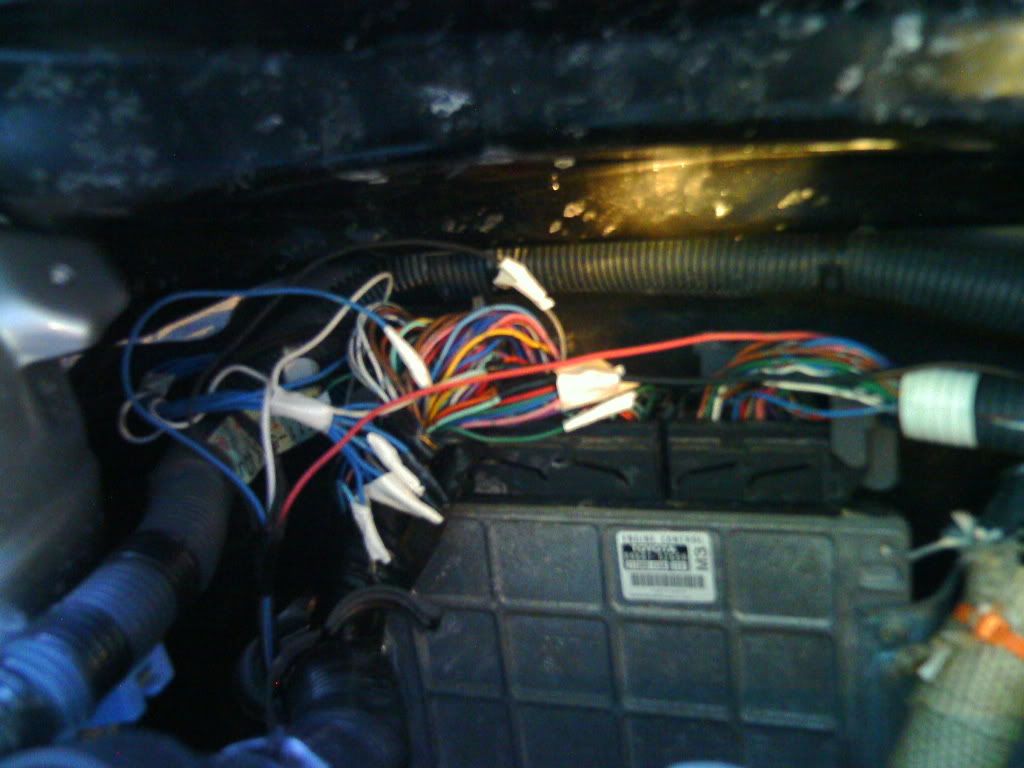
Last edited by Focus_Sh1ft; 11-21-2012 at 12:53 PM. |

|

|
|
|
 Similar Threads
|
||||
| Thread | Thread Starter | Forum | Replies | Last Post |
| Tamago's guide to ultimate yaris handling | Tamago | Wheels, Tires and Suspension Forum sponsored by The Tire Rack | 98 | 02-18-2024 05:45 AM |
| Zage Turbo Kit Install - Toyota Yaris | Focus_Sh1ft | Forced Induction Forum | 160 | 02-06-2022 08:14 PM |
| Compilation of Yaris How-tos/DIYs | YarisBueller | DIY / Maintenance / Service | 39 | 04-28-2018 08:47 AM |
| Complete Racing Seat Install Guide | advocate | DIY / Maintenance / Service | 7 | 11-25-2009 02:26 AM |
| HKS turbo timer type 1 | Tamago | Performance Modifications | 3 | 07-21-2009 11:59 AM |


 Threaded Mode