Quote:
Originally Posted by birdman

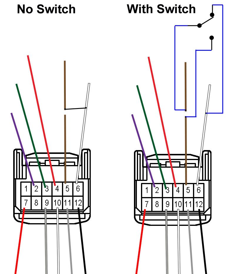
In post #115 the diagram shows the brown wire is cut. The upper part you have pictured connected to a blue line going to one side of the switch. On the other side of the switch there is a blue line that splices to a white wire. The portion of the brown wire that is attached to the connector you show a blue line attached to it. That blue line terminates at a black dot. If the black dot doesn't indicate a ground then what does it indicate? There is no mention of a +5v line in that diagram. This simple diagram isn't simple to me.
|
The black dots just indicate connection points. What the diagram below shows is that the "common" for the switch goes to the wire that heads up to the cluster and the two "poles" of the switch connect to the brown wire (for normal operation) and the white wire (for bypass operation). So, the switch is simply connecting the wire up to the cluster to the output of the module (the brown wire) or +5V (the white wire).
In your post where you mentioned ground, I just wanted to clarify that there is no ground connection with the switch, as making such a connection would instantly pop a fuse.


 08-02-2010, 08:30 AM


 Similar Threads


 Threaded Mode