
 |
 |
 |
|
|
|
#1 | ||
    Drives: 08 Yaris Turbo; 06 tC Turbo Join Date: Jan 2010
Location: New Jersey
Posts: 875
|
Zage Turbo Kit Install - Toyota Yaris
*Would really appreciate if a mod could sticky this. I want this to be SEEN. Thanks
Alright guys, here it is as promised – the ZAGE Turbosystems install guide for the Toyota Yaris. I was obliged by Zage to put this together, but I'm really hoping this helps some people take the plunge like I did. It's very much worth it in the end. Even for those that don't use this kit, there should be a lot to learn from checking out this guide. I also feel it's necessary to point out that the quality of this kit is superb (well, for the most part). There were a couple fitment issues, but nothing was a deal breaker. People may say sucky things about their turbos, but I'm quite happy with it. I haven't had any problems with it, and it's the perfect size for our small cars. Before I get into the actual install, I’d like to point some things out. To begin, this should be the LAST thing you do. Whether you followed my pre-install guide(http://www.yarisworld.com/forums/showthread.php?t=30813) or not doesn’t matter, but all the things listed in there are a necessity to getting boosted successfully (turbo timer being the potential exception). *YOU NEED TO CHANGE TO A SMALLER GAPPED SPARK PLUG. I swapped in NGK BKR7EIXs with a .032" gap. If you don't you're going to have misfires at mid/heavy load. Also – this is an incredibly lengthy and difficult installation. If you’re on the fence about all the work required to pull this off, stop here. You need to WANT this. You need to want this more than the fat nerdy kid wants to lose his v-card by the end of senior prom. Yeah, THAT MUCH. You’re going to get so worn out and sore and get soooo many cuts (my hands are still healing). You’ll get over it though, because I can safely say the end justifies everything. I would say it took me approximately 4 six-hour days to finish the install. Troubleshooting and leak diagnosis made it take a couple days longer. Mechanical expertise would probably be a plus, but is not at all required. I’ve never done anything this involved before, but I made it work. As long as you’re not a total idiot, and are capable of learning and using your brain, you’ll be fine. Luckily for you, I’ve already done most of the thinking during my install. However, something this complicated has many variables that are going to vary from install to install. This is where that brain that is required comes into play. Tools… ARE EVERYTHING. You need tools, lots of tools. Tools, tools, tools. TOOLS. They’re kind of important. The more the better. I ended up borrowing some, because the difference between having the right tool and not having the right tool are staggering. The absolute necessities are a metric and English socket set (any ratchet size should be fine) and a metric and English wrench set (preferably open and box). Some larger Philips and flat head screwdrivers will be needed as well. Pliers for a couple of OEM clamps, and exacto knives for cutting hoses and misc uses. A hacksaw will also be needed in a couple of places. You’ll be needing a drill with (preferably) a set of bits. I didn’t really note which ones I needed. Definitely a rubber mallet and some sort of pipe for leverage on wrenches / ratchets. A M4 female torx socket or vicegrip will be needed eventually. I think that covers what I used MOST of the time. Beyond the wrench and socket sets, you could possibly replace the others with other tools if you’re creative enough. Oh, and of course an oil drain pan and funnel. Here are the following items you should have on hand before beginning the install: -Permatex Ultra Black Silicone Sealant -Teflon Paste (USE ON ALL THREADS THAT SEAL HOLES) -Paper towels -Zip Ties -Some sort of mounting brackets (see STEP THIRTY-THREE) -A SERIOUS drill bit (about ¼”) (see STEP THIRTY-THREE) -Tooth picks (or similar; used to spread silicone) -Exhaust Wrap -3x 5/16” nylon tees -6-8 feet of rubber hose (fuel hoses should work for vacuum and coolant) -8x Small hose clamp (Advance Auto part #7090227) -2x M8-1.25 x 40MM (could be shorter) hex bolt (CB#36008) -> Intercooler -2x M12x1.25 to 1/8" NPT female* -2x 1/8" NPT male to 5/16" barb (Advance Auto)* -AC refrigerant** -Code Reader*** *Only needed if water cooling turbo. Skip step 19, 45, and 47 if you're not water cooling the turbo. **You may need to move the AC lines to fit the turbo in. You’re welcome to find alternatives, but it’s easier to just drop $20 so they can be moved and recharged afterwards. Some people have done it without moving them, but I still don't understand how. ***In retrospect, I made a huge mistake not having a code reader immediately handy. You’re very likely to get codes for one reason or another, and it’s vital to know what they are. Don’t be like me where you’re driving back and forth between Advance Auto just to have codes read. PAY CAREFUL ATTENTION TO UPDATES. STEP ONE: ---Remove engine cover -It’s held on by 2x 10mm capped hex nuts. 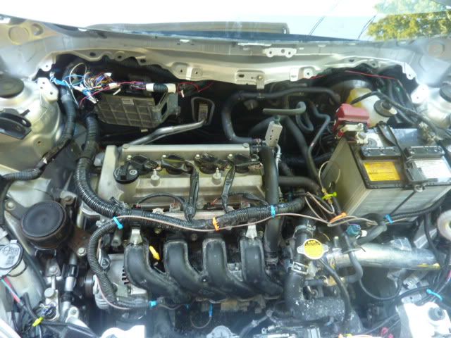 STEP TWO: ---Remove exhaust shield -There are 4x 10mm bolts, two up top (use a socket) and two at the bottom (use a box wrench). 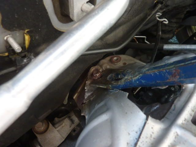 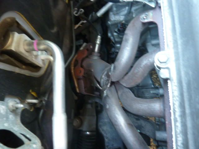 STEP THREE: ---Unbolt OEM manifold -I believe there’s 3x 10mm bolts and 2x 10mm nuts at the sides (if not, they’re 12mm). You should be able to reach everything with just a socket and the necessary extensions. If not, use an open/box wrench. Save these, we’ll be reusing them. 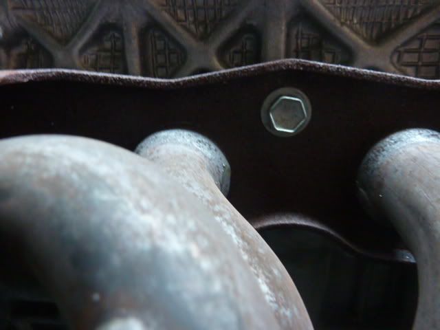 STEP FOUR: ---Unplug the O2 sensor. -The plug is mounted on a metal perch at the back right side of the engine. Unplug it. UPDATE: I had a talk with my tuner who works on my other car regarding leaving an O2 sensor in while unplugged. If you're going to be tuning in open loop with an unplugged O2 sensor (like I did), remove the O2 sensor from the piping. The carbon builds up heavily on the sensor since the heater is no longer functioning and will cause it to completely fail eventually. STEP FIVE: ---Jack up the car STEP SIX: ---Unbolt the header from the exhaust system -You need to be under the car to do this. There are 2x 14mm bolts (TIGHT) that are backed by springs. Here’s a picture of them, and the best way to get at them. The picture is slightly unclear, but I basically used an extension that allowed me to clear the black frame under the primary cat. Use leverage and a rubber mallet. 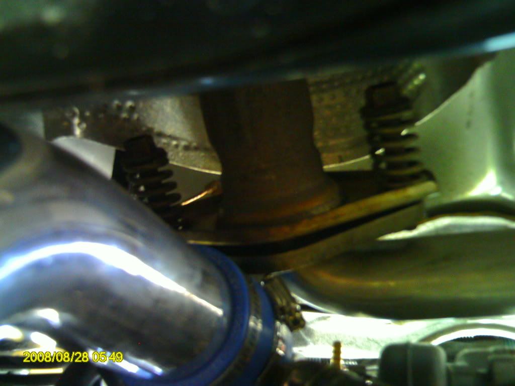 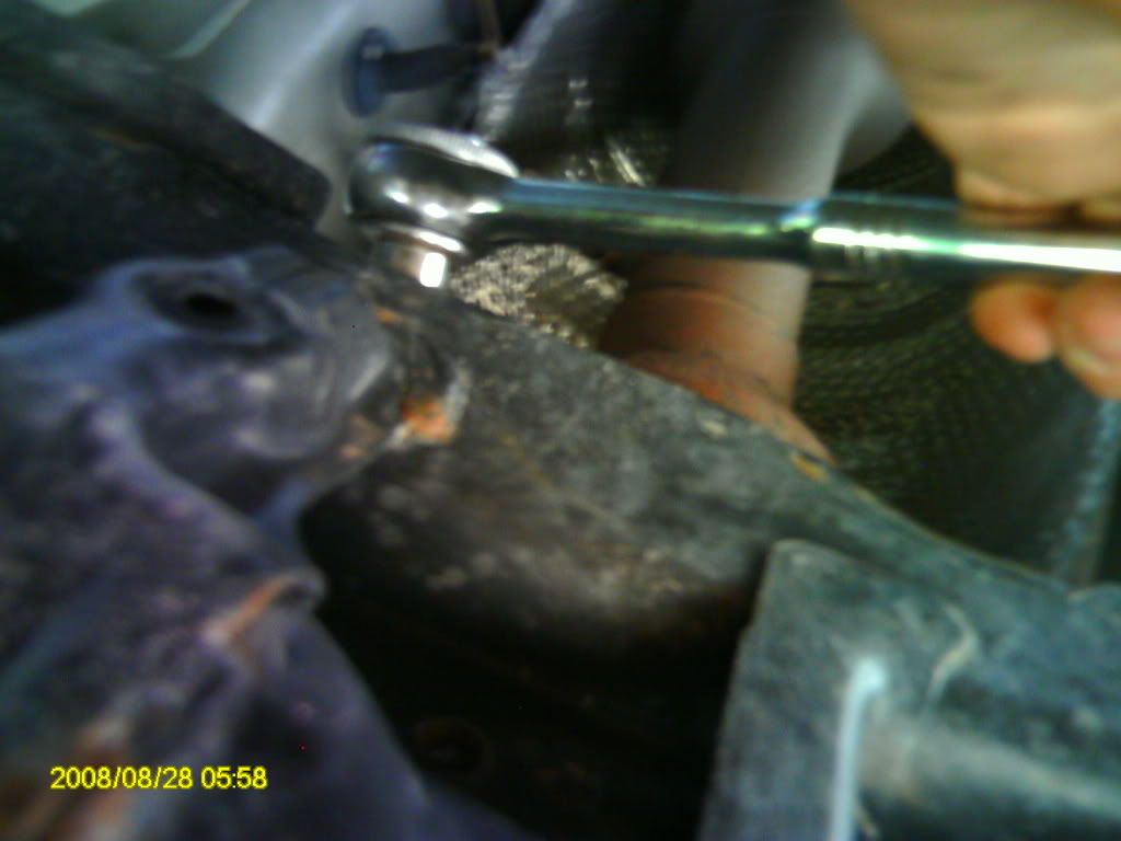 STEP SEVEN: ---Remove 2x black frame header supports -Removing these sucked so bad… They have to come out as well. The longer frame piece is held on by 2x 14mm bolts, and the squarer frame (with the x shaped engraving) is held on by 1x 12mm nut and 1x 12mm bolt. These bolts are excessively tight, and incredibly difficult to reach. The approach I take in these kind of situations is to first try to get a socket on it, apply some leverage, and hammer the leverage with a rubber mallet if possible. If not, I resort to the box wrench. Open wrench last. Also keep in mind, and this will come in handy later as well, that you can use a normal socket on a nut that would usually require a deep socket. Just put the socket on, then push the square connector into the socket as far as it will go. On EVERY nut in this install it will be able to engage the socket enough to tighten/loosen the nut. 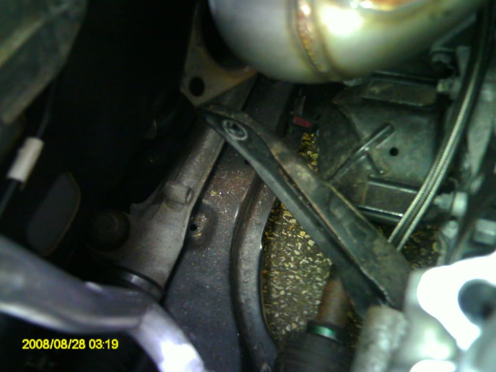 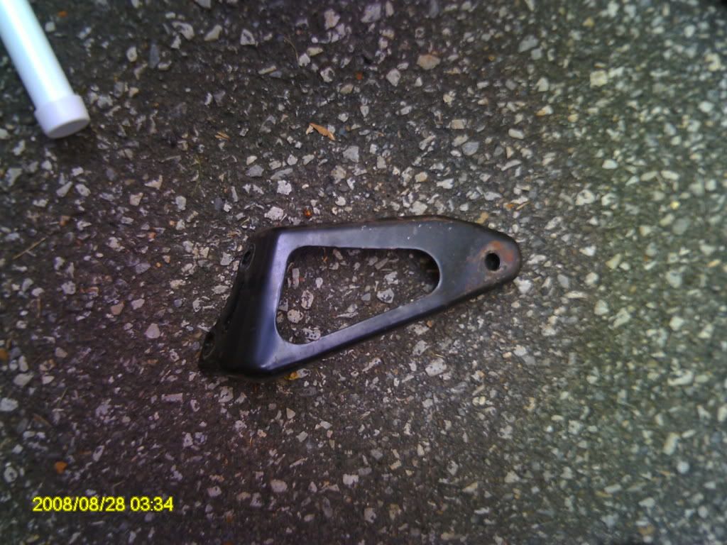 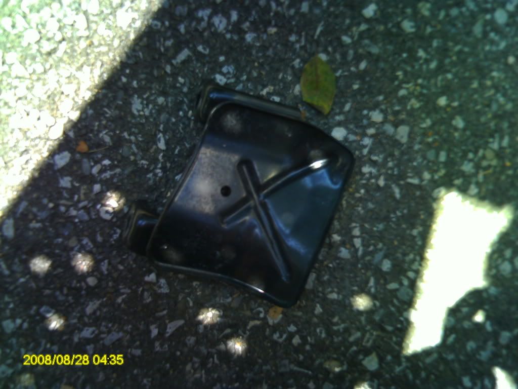 STEP EIGHT: ---Lower car STEP NINE: ---Remove header assembly -We unbolted everything attached to it so work it out of the engine bay. Make sure to take the gasket off and save it for later. In all honesty, I didn’t even realize there was a gasket and ended up putting it in later.  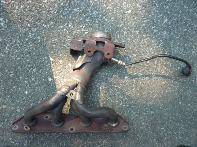 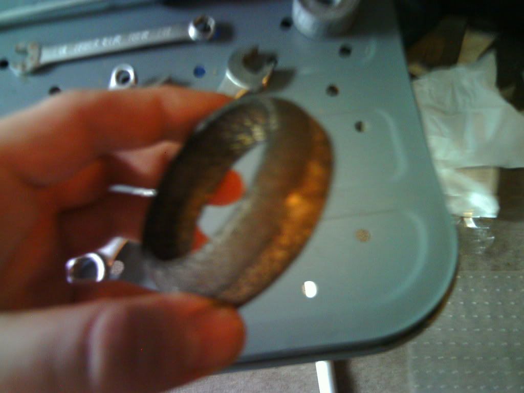 STEP TEN: ---Remove O2 sensor from header bung -I used a 7/8” box wrench (yes, it fits over the plastic connector). I put the header on the ground, put one foot on it, then used a rubber mallet to get the sensor bolt moving. 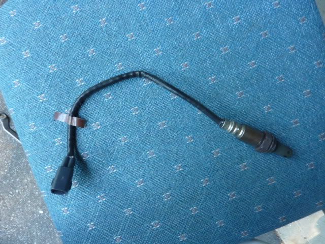 STEP ELEVEN: ---Remove vacuum hose -Back right side of engine. This needs to be moved out of the way for when we mount the turbo. In the picture, it’s the hose that runs behind the beige plastic connector. 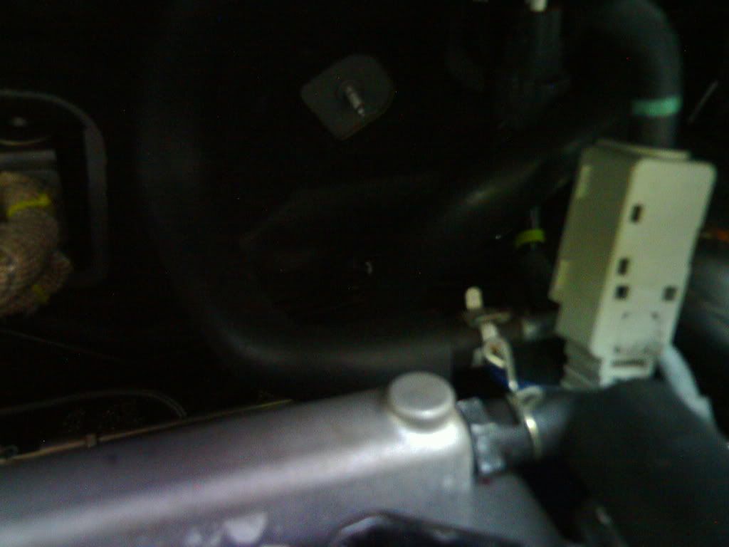 STEP TWELVE: ---Remove O2 sensor perch -I don’t know if this is totally needed, but there really won’t be a need for it. Plus, it’s in the way. You may actually need to remove this sooner to have clearance to get the OEM manifold off. The bolt is 14mm and cannot be wrenched off until you hit the perch a few times with a regular hammer (otherwise the bottom of the bolt is touching the perch). STEP THIRTEEN: ---Move AC lines -Loosen the 10mm bolt that holds them in. More than likely, the o-ring will blow on the upper line and leak refrigerant everywhere. If not, just loosen the bolt and pull the line out and step back. Next, we need to remove the 10mm nut that connects on the upper line (its near the wiper fluid tank). Lastly, remove the 10mm bolt that mounts the lower line (its near the alternator). It’s too hard (and unnecessary) to remove the lines, so just move them to the side, placing them in front of the ECU. 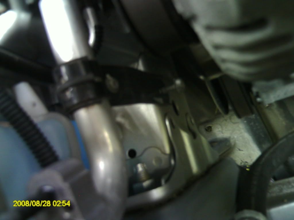 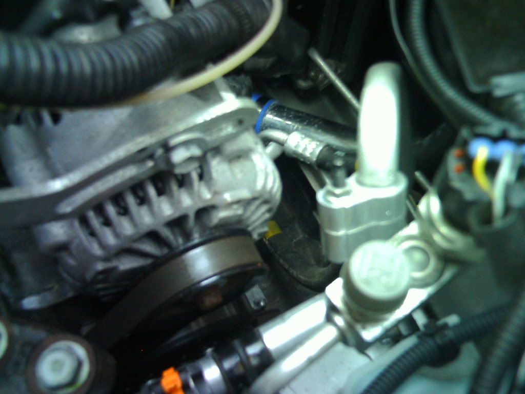 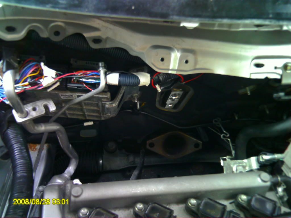 @At this point, you’ve pretty much removed all the necessary parts. It’s time to begin assembling the turbocharger. Bust out the Zage kit. STEP FOURTEEN: ---Mount turbocharger onto manifold -Make sure the turbocharger is oriented downward. The tabs on the manifold should face upward. Put the flange between the manifold and turbo, then place the bolts in and get them threaded by turning them with your fingers. Take a ½” wrench and tighten them to the point where they won’t turn anymore. 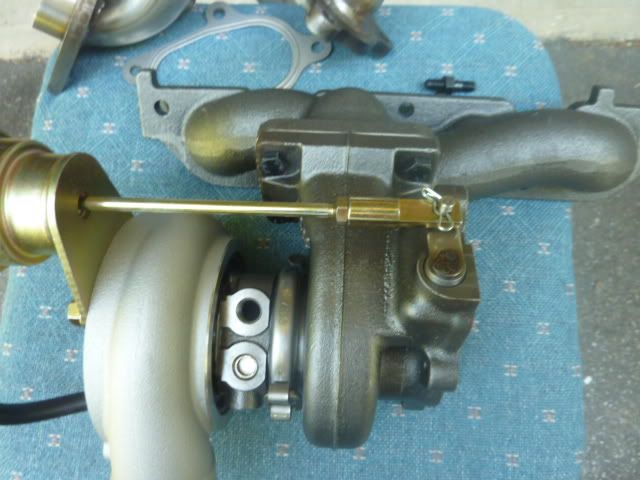 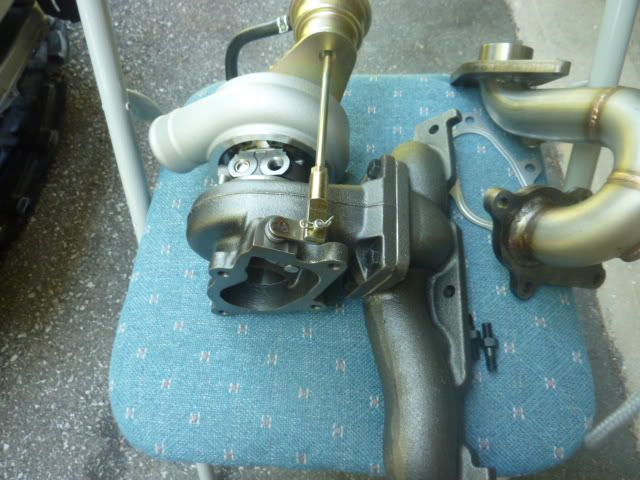 STEP FIFTEEN: ---Mount downpipe on turbocharger -Same procedure as mounting the manifold. Make sure you place the flange between the downpipe and turbo first. Then use the four black bolts that have nuts on them. The short side of the bolt is the side that goes in. Tighten the bolts with a ½” wrench. 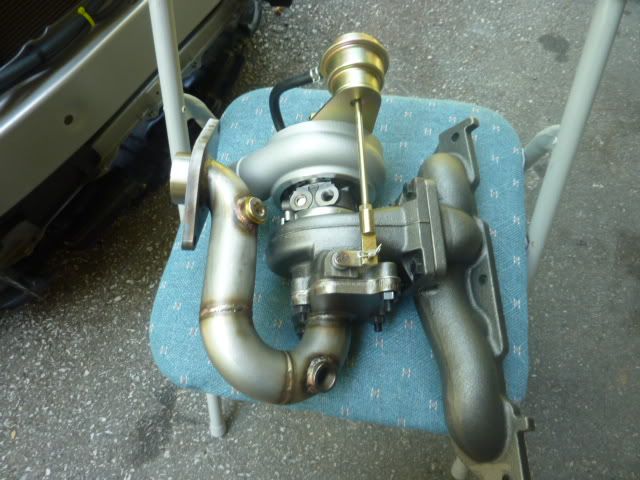 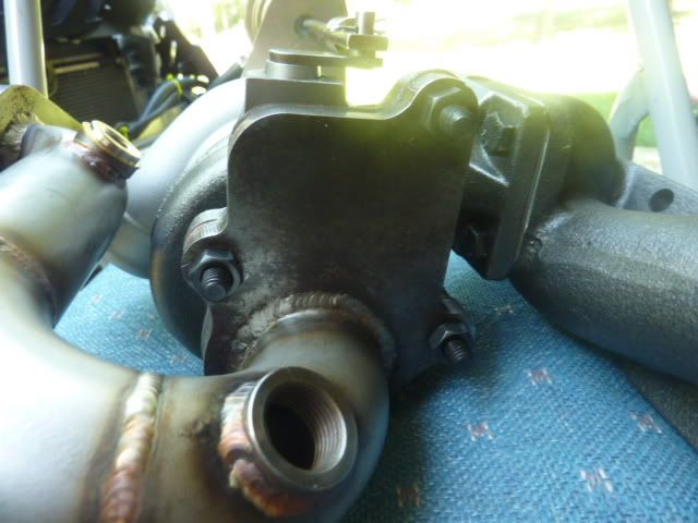 STEP SIXTEEN: ---Place O2 sensor in Zage downpipe bung -Use a 7/8” box to get this tight. If you’re installing a wideband sensor as well, you’d have to open the other bung with an allen wrench (size: M10). Also - the AEM UEGO sensor is a perfect fit in the other bung. Use 7/8" open to tighten it. 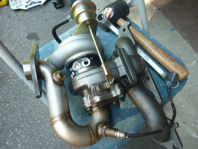 STEP SEVENTEEN: ---Attach oil return line adapter to turbocharger. -Grab the silver adapter bolt, two of the brass screws, the ovular adapter plate, and the black foam(?) flange (the one with the tab on one end). Put the flange in place, then bolt on the adapter plate with the 2x 10mm (?) brass screws. MAKE SURE THESE SCREWS ARE TORQUED EVENLY. I had a leak because they weren’t. Would also suggest putting some silicone on the part of the flange that faces up. I then used a 7/8” box wrench to tighten the adapter nut in place. Next you need to connect the 45 degree brass elbow. I got it tight by gripping it with pliers. Lastly, connect the oil return line to elbow (it’s the thicker steel braided line), and tighten by hand. Then get it tight using a 15/16” open wrench. 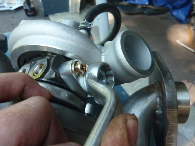 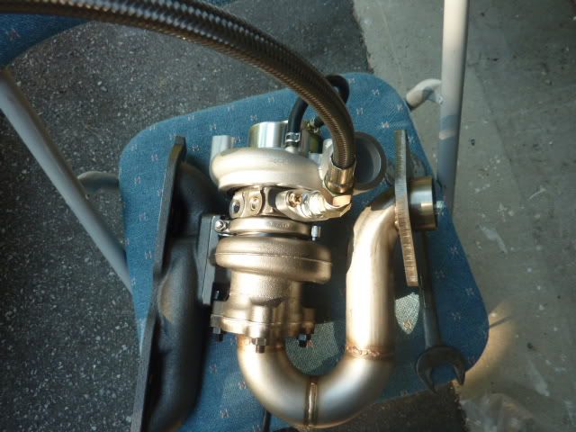 STEP EIGHTEEN: ---Attach oil feed banjo bolt to turbocharger. -This thing was a pain to get tight, and ended up being pretty leaky for me in the end. Anyways, you need to put the bolt through the loop on the banjo bolt, then thread it into the turbo. There needs to be one washer on each side of the loop. Tightening this thing is near impossible, but if you spend some time working at the 17mm bolt with an open wrench, you can still get it pretty tight. Attach the oil return line, and then tighten it using a 9/16” wrench. 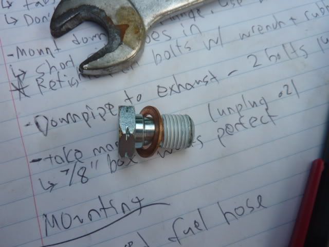 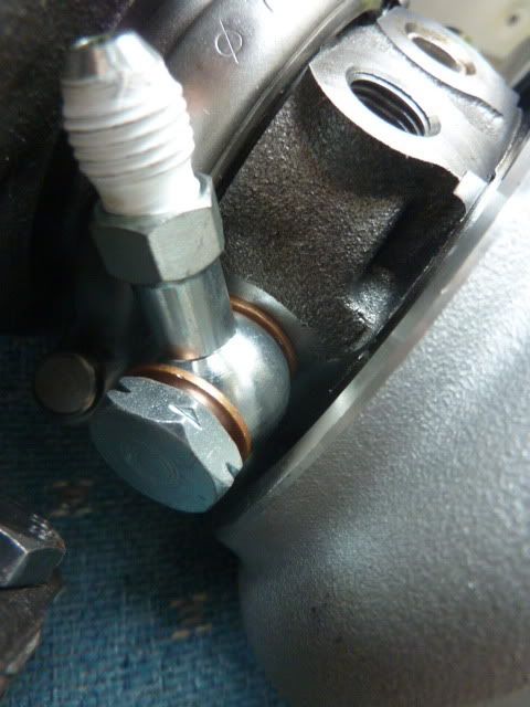 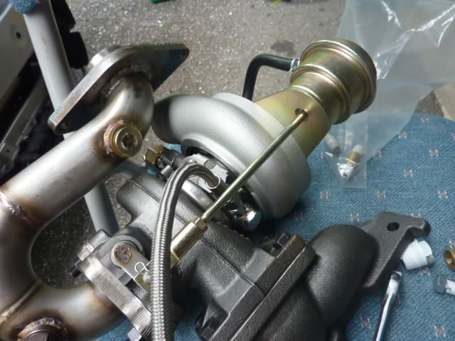 *It’s very likely you’ll be needing to disassemble the turbocharger to get the banjo bolt tight enough (A 17MM SOCKET WILL NOT FIT). In fact, I’d recommend it, because it’s the reason why I had to pull my turbocharger off the engine. The clamp that holds the turbine and compressor housings together needs to come off (it’s 10mm). There’s also a clip that holds the actuator arm in place. Just make sure when you put them back together that the compressor inlet is facing the exact same way as it was before (you can do this by keeping the actuator arm straight). 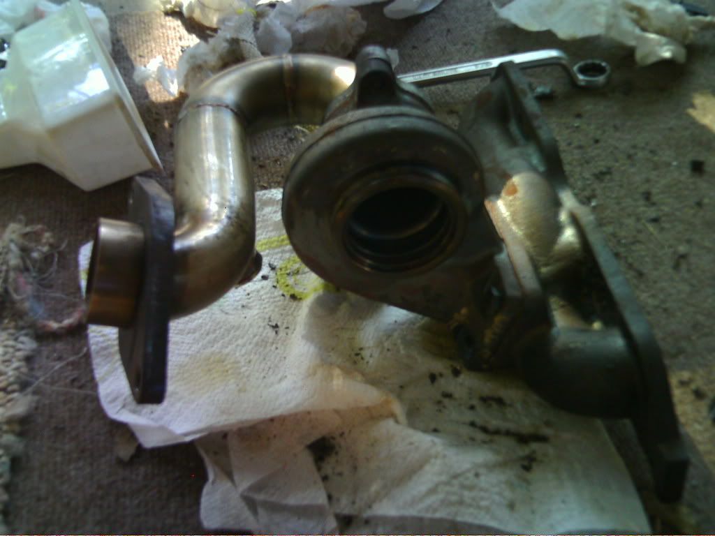 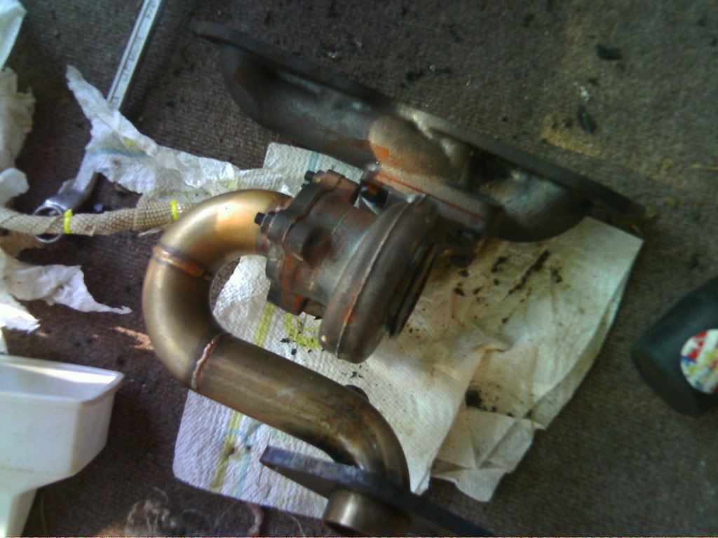 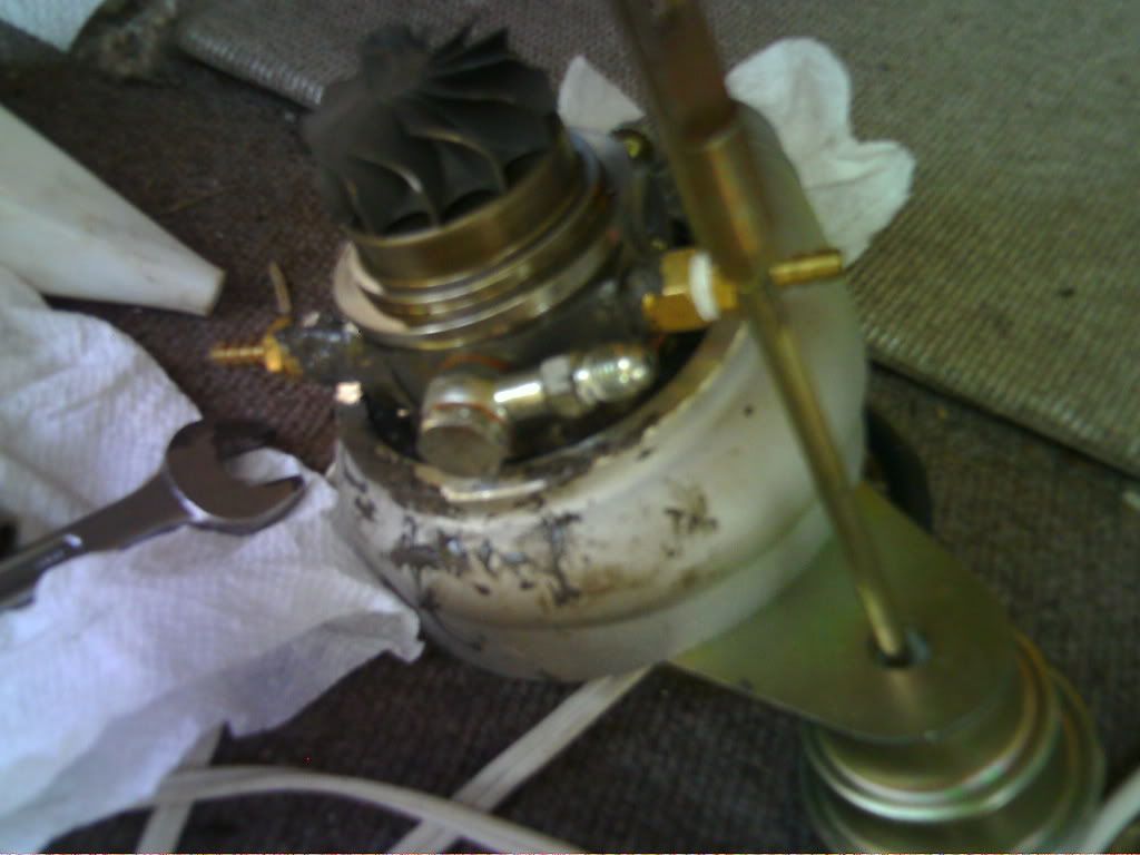 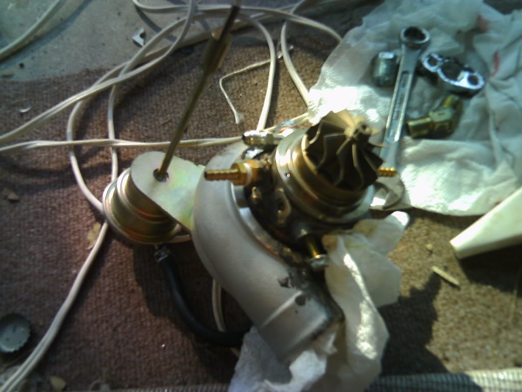 STEP NINETEEN: ---Attach coolant line adapters (if using water cooling) -Assuming you’re water cooling the turbo, and you should be, connect your 1/8” barb to the M12 female adapter. Now, based on my experience, I would recommend only placing the one adapter in that will be facing downwards. If you place both in, one ends up getting caught on the engine/firewall as you try to fit the manifold / turbo / downpipe into the engine bay. Feel free to try placing both in though. Also, attach your coolant line to the bottom adapter now, otherwise it’ll be impossible to reach later. I used a small t-clamp here.. You don’t need a hose on the top adapter for now, but the bottom one will need about three feet of hose. STEP TWENTY: ---Mount the turbocharger assembly to the engine. -With all the above crap we removed, this should only require a bit of wiggling to get it behind the engine. Once you have it approximately in place, hang the manifold flange from the two stems that the manifold bolts to. Then, attach the manifold using the OEM bolts and nuts. Just get the bottom two hand tight, but get the two nuts and one bolt in the middle top tight with a wrench/socket now. The former two bolts need to be tightened from underneath the car, so we’ll get back to that later. Don’t worry about plugging the O2 sensor in quite yet. 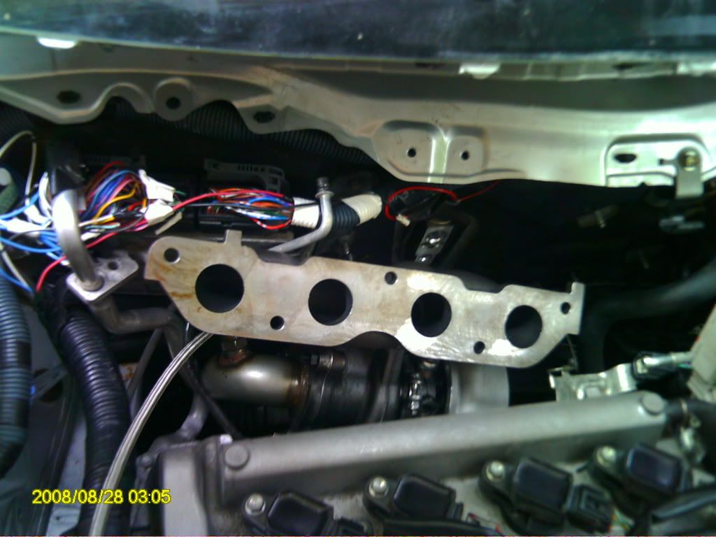 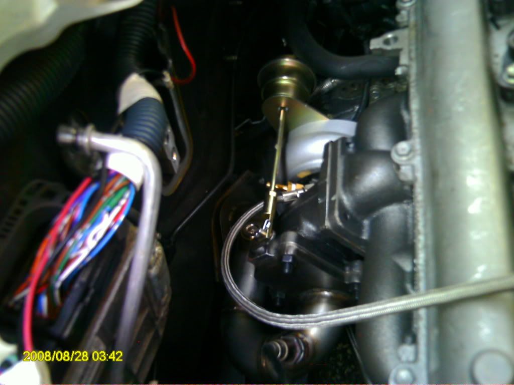 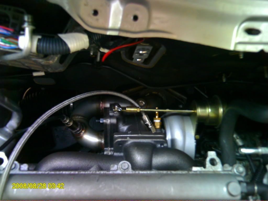 STEP TWENTY-ONE: ---Raise the car STEP TWENTY-TWO: ---Trim one of the exhaust bolts (the ones with the springs) -So the downpipe is ready to be bolted on, but we have to deal with this first. Basically, the bolt on the right side of the exhaust ends up hitting the downpipe once its threaded in enough. All I did was place the bolt in a clamp and cut off approximately ¼” of the bolt. You really could cut as little as 1/8”. I used a hacksaw, then sanded the cut edge down slightly with a power sander. 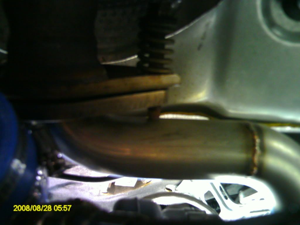 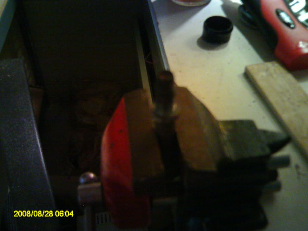 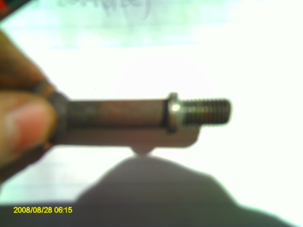 *Would like to point out that after pulling these bolts out of the exhaust assembly about three times, the holes that the wider part of the bolt sits on (so the spring can engage) widened and they fell through. This left a gap between the downpipe and exhaust assembly because the wide part of the bolt acts as a spacer more or less. This is an easy fix, and you may want to do it right now – grab a wide washer that fits around the bolt. STEP TWENTY-THREE ---Attach Zage downpipe to exhaust system. -See Step six. Same procedure but backwards. I shouldn’t have to say this, but get them tight.  STEP TWENTY-FOUR: ---Finish tightening manifold bolts -Now that the car is raised, it’s possible to get the two lower manifold bolts tight. They’re hard to get at still, but if you reach up past the axle you should be able to get an open 10mm wrench on them. 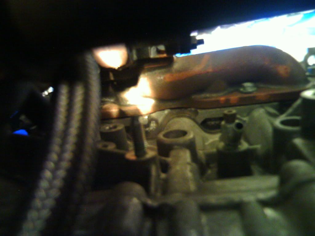 @You should have the turbocharger assembly fully mounted at this point. Don’t worry about the oil and coolant lines yet, we’re going to do piping first. STEP TWENTY-FIVE: ---Mount first pipe to turbocharger -The way I prepared these pipes was by placing a silicon coupler on each side, and clamping it to the pipe with a t-clamp. Then I add another t-clamp to the open side and tighten it enough just so it stays in place. That way, when you connect a pipe, all that is needed is to push it into the silicon coupler and tighten the t-clamp. Grab the pipe in the first picture, prep it, then get under the car and connect it to the turbine housing on the turbocharger. Try to arrange the t-clamp bolt so you can reach it with an 8mm box wrench. You could also use a flat head, but I found the box much easier. 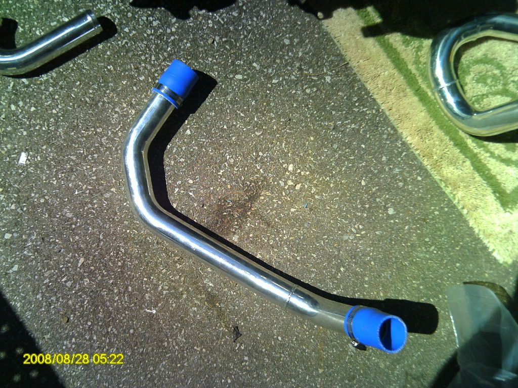 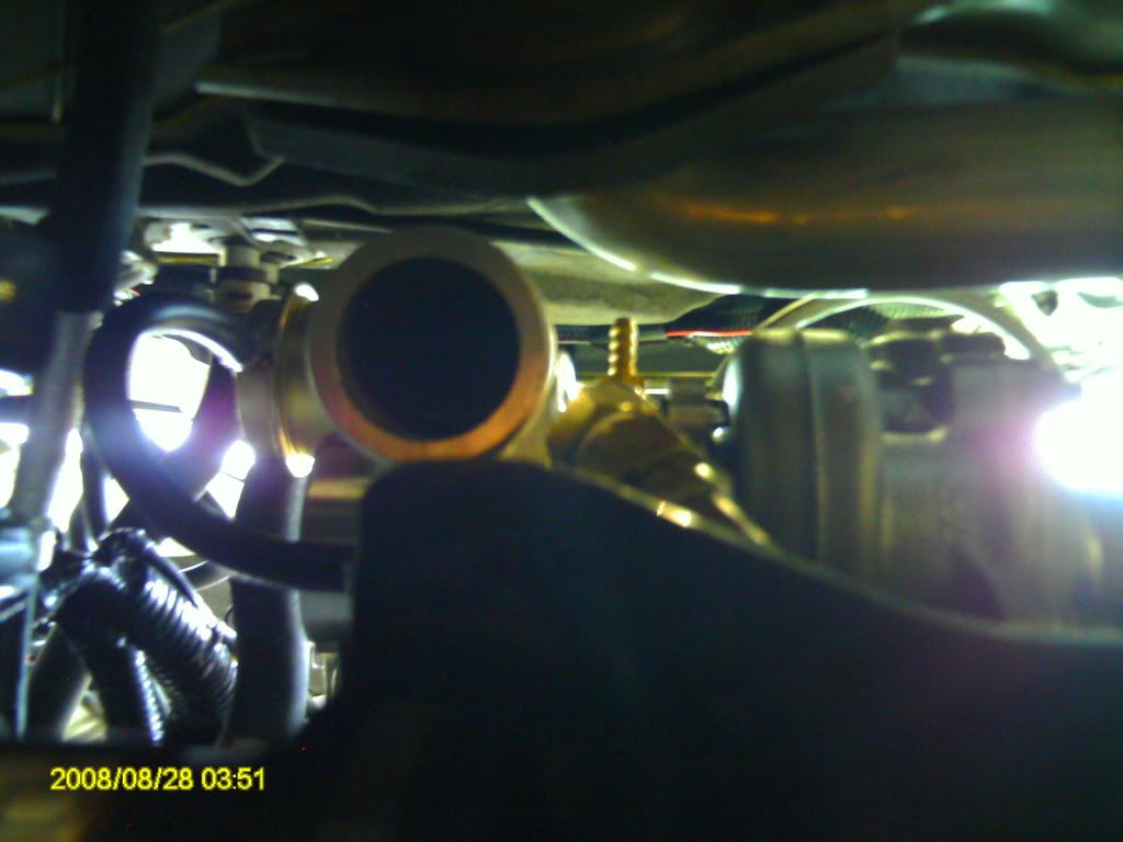 STEP TWENTY-SIX: ---Remove/cut black plastic next to radiator -You’ll see what I mean in the first two pictures. The only part that really needs to be dealt with is that bottom part, because the next pipe we connect has to run through where the plastic is. I didn’t remove the whole piece, as I thought it would expose an unnecessary amount of the engine bay. I used a combination of drilling and hacksawing to remove the plastic. 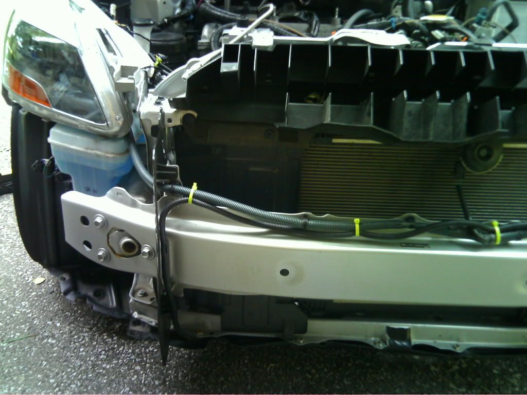 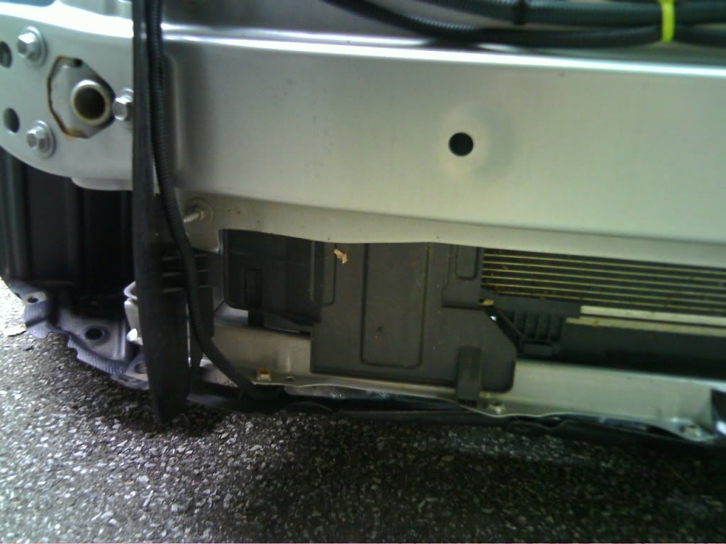 STEP TWENTY-SEVEN: ---Connect second, J-shaped pipe -Grab the J-shaped pipe (not the one with the bung for the blow-off valve) and prep the shorter side (this side will connect to the intercooler). Afterwards, connect the longer side of the “J” to the piping that’s coming off the turbocharger. Make sure to tighten the t-clamp. 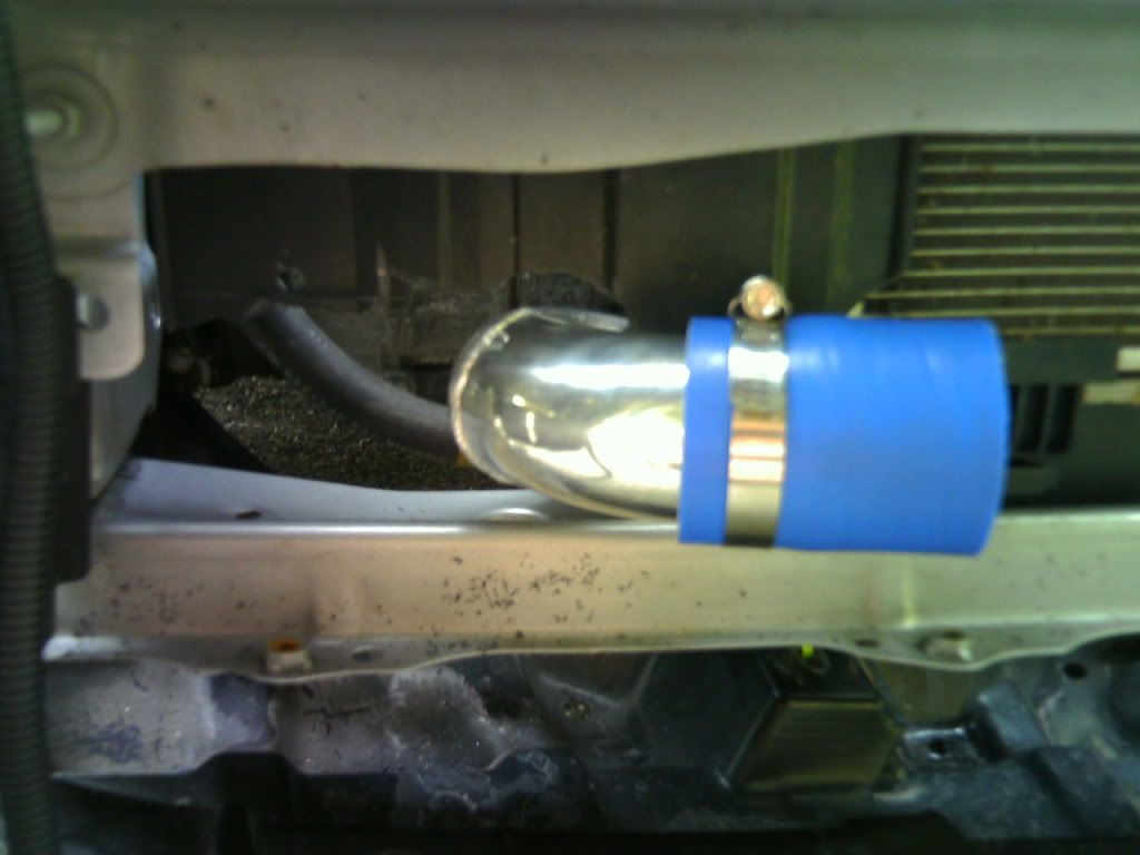 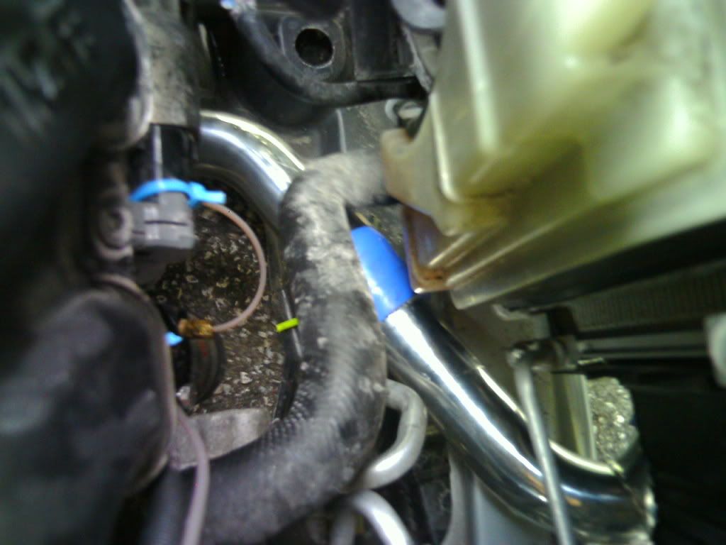 @I found it best to save the intercooler for last, especially because it has fitment issues. For now, we’ll start the piping off the throttle body. STEP TWENTY-EIGHT: ---Remove current air intake system -Obviously, this will vary. I had a cheapo could air intake that was easy to pull out. I would like to think that if you have an aftermarket intake installed, you’d also know how to UNINSTALL it. If you have the factory air box, I believe the top clips off and you need to pull the filter out to expose the two bolts that hold it to the frame. They’re most likely 10mm bolts. Put the MAF sensor aside for now. 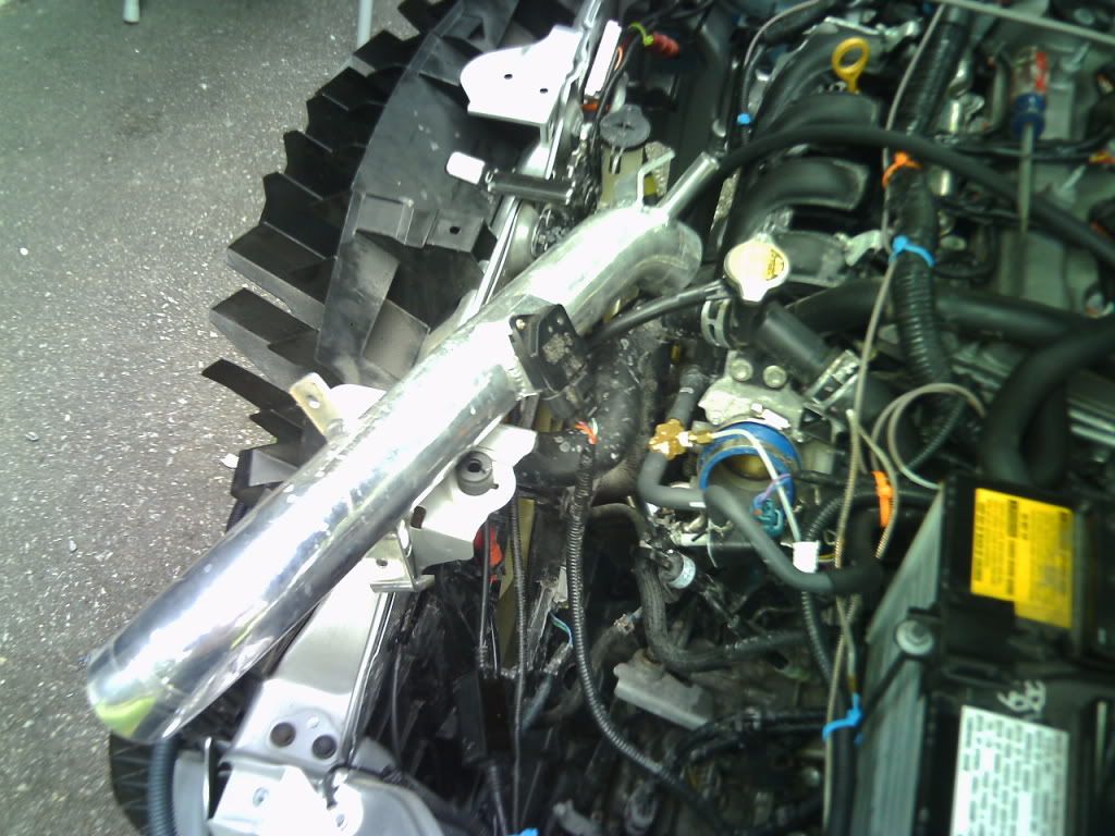 STEP TWENTY-NINE: ---Attach blow-off valve to throttle body piping -*UPDATE: I recommend a third party BOV. Zage's kind of sucks. -This is the other J-shaped pipe, but with the bung. Grab the noticeably smaller silicon coupler and 2x t-clamps that will be used to mount the blow-off valve. Install it exactly as it is in the following picture (make sure the hose barb is facing up). Place the pipe in the throttle (not too far, otherwise the throttle plate will hit the pipe), and tighten t-clamps. 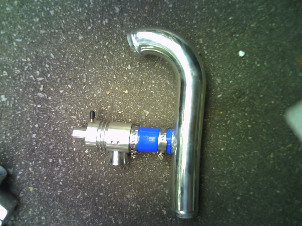 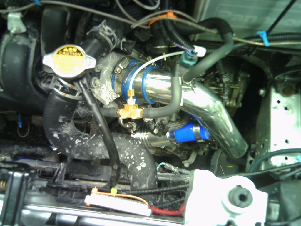 STEP THIRTY: ---Cut right bumper support for piping -You’ll see what I’m talking about in the pictures. All you need to do is snip the tabs where the hole is, and enough of the plastic support will fall away to allow the piping to fit. This will also retain one of the clips that hold the black plastic support into the actual steel bumper support. 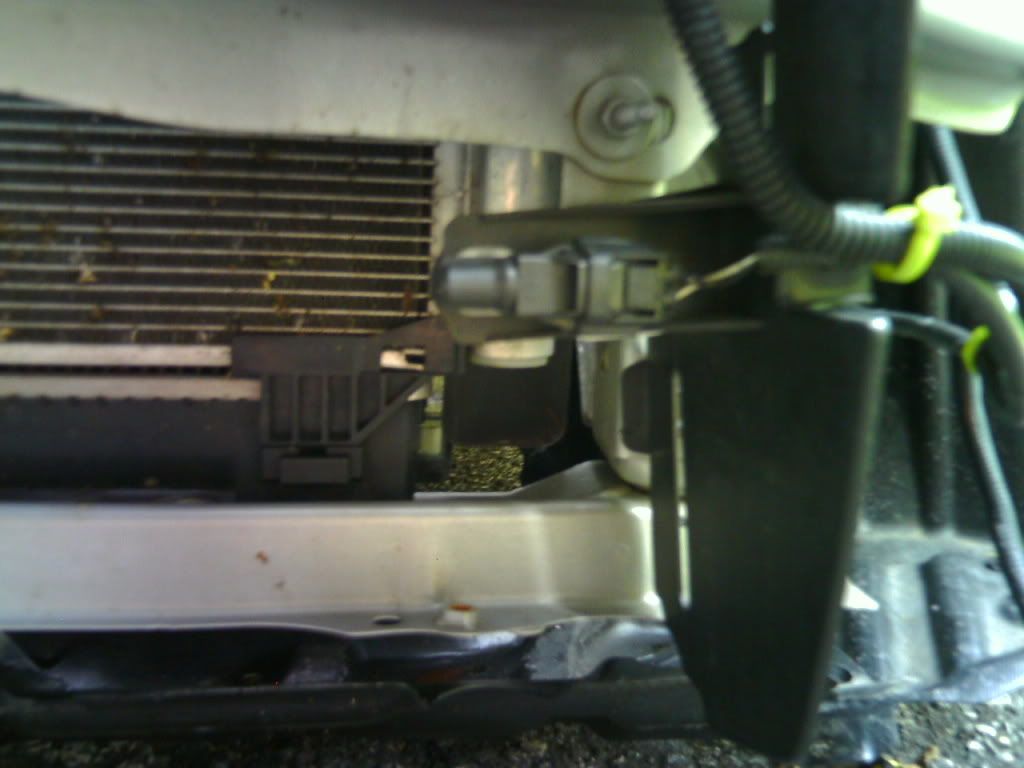 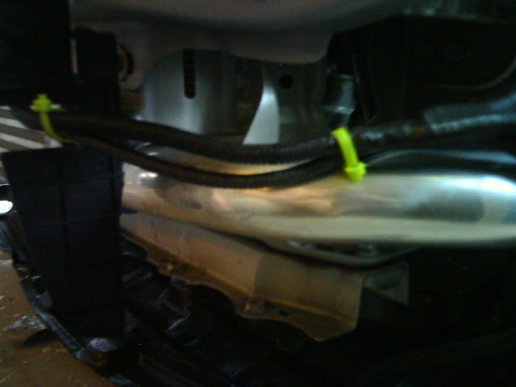 STEP THIRTY-ONE: ---Attach throttle body piping to right intercooler piping -At this point you should be down to two pipes, one that’s incredibly wacky shaped, and another with a hole for mounting the MAF. You need the wacky shaped pipe. Put a silicon coupler and t-clamps on the side that doesn’t bend upwards (will attach to the intercooler). Push pipe up into throttle body piping’s coupler, tighten t-clamps. 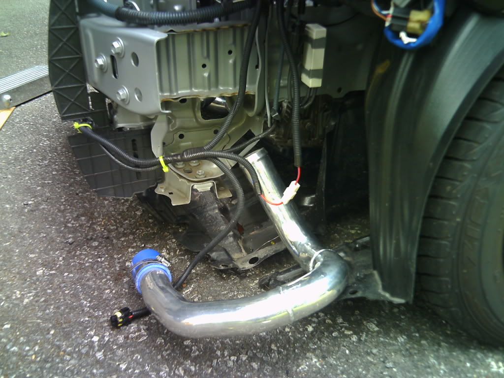 STEP THIRTY-TWO: ---Attach intercooler -Fitment on this thing kind of sucks. You’ll notice the intercooler outlets are in different spots too (one in the middle, one on the top/bottom). I’m unsure of the proper way to connect this, but I put the middle outlet on the left, and the bottom outlet on the right side. Attach one side at a time by tightening the t-clamps. Yes, it sits lopsided, but this can be fixed. 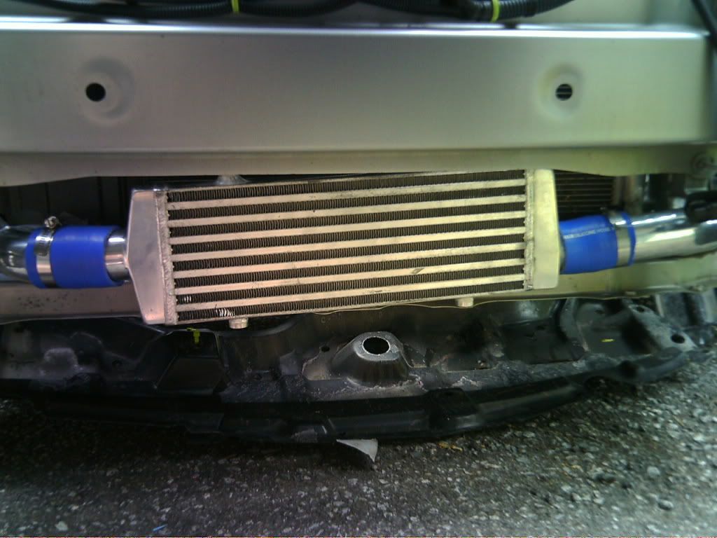 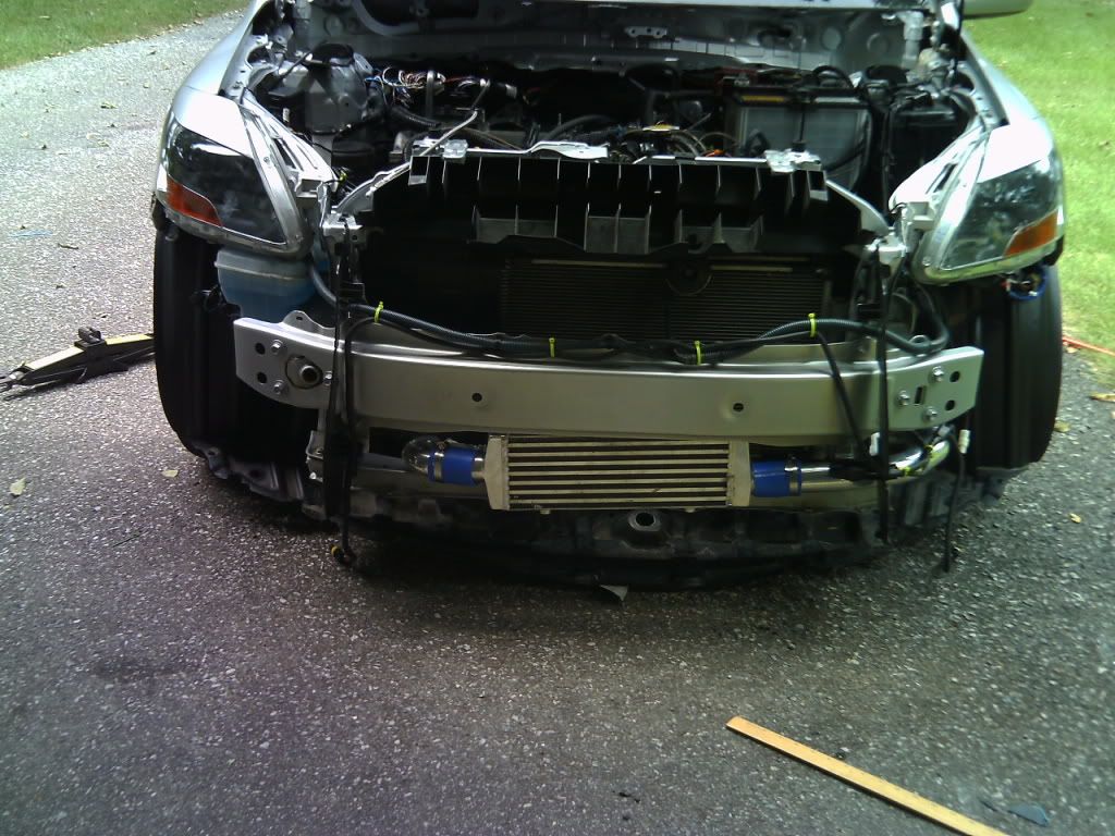 STEP THIRY THREE: ---Design mounting brackets for intercooler -The way Zage mounts their intercooler is by drilling holes in the bottom of the bumper support, then using the bolt holes on the top of the intercooler. I have no idea how they did this, because as you can see in the first picture, the intercooler is terribly off of the bumper support. This can be solved a number of ways. I had these generic brackets sitting around that come in a roll that you cut to the size desired. I then drilled the holes slightly larger in the brackets so the intercooler bolts would fit. For now, I’ll leave this up to your creativity. I’d also like to point out you could use 5 zip ties (each side) to wrap around the silicon couplers and bumper support. This is probably, at best, a temporary solution though. 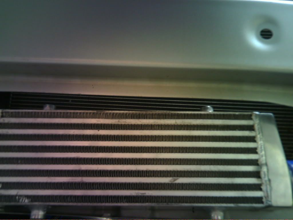 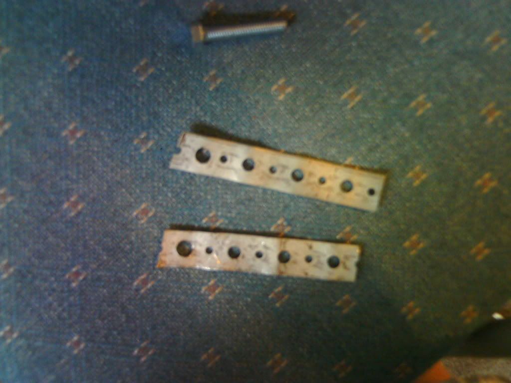 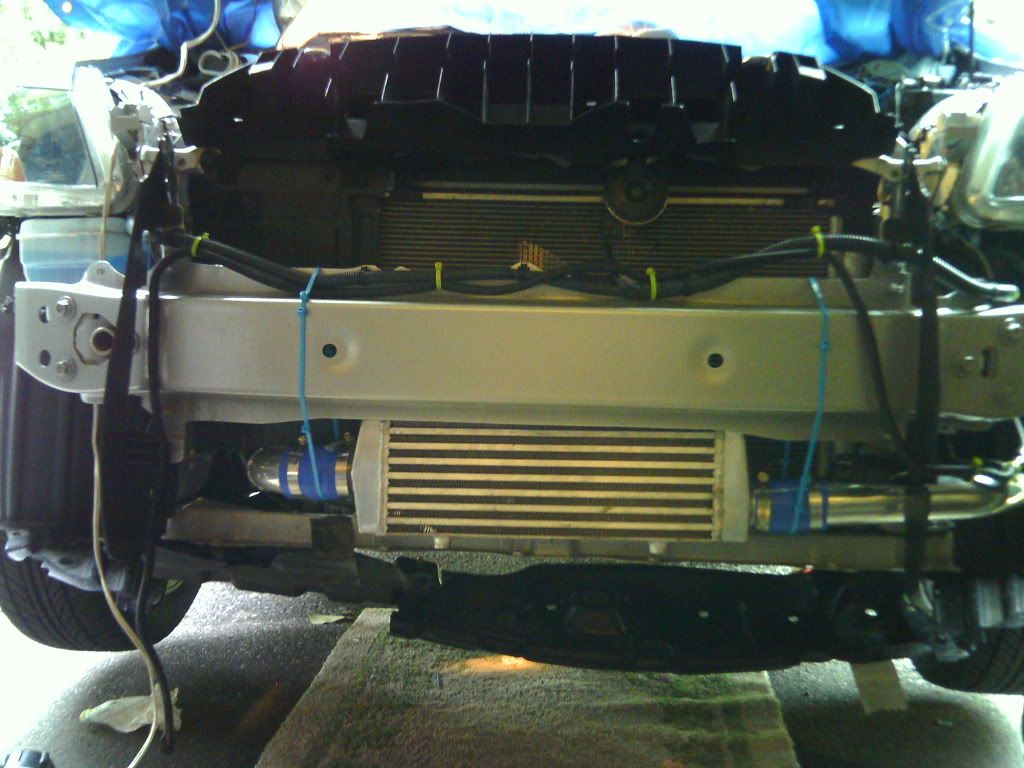 *UPDATE: I bought a carbid drill bit and still couldn't get through the front bumper support. I ended up drilling two holes in the thin metal portion where the skid plate bolts up. I then bolted the above brackets to the bottom of the intercooler. It's much more firm (and level now). You could probably avoid drilling and just use the holes that are already there. I'll get some pictures sometime. @Piping is now finished. It’s time for arguably the most difficult part – running the oil/coolant/vacuum lines. STEP THIRTY-FOUR: ---Drain engine oil -If you’re doing this install, you’ve probably done an oil change before. If not, you need to grab an oil drain pan (also a funnel for later) and place it below the oil pan. Off-center of the pan is a 14mm bolt that is the drain plug. Unbolt that and let the oil drain into the pan. Next you need to remove the filter (I’m going to assume you have the sandwich adapter from my gauges guide installed). Usually I can grab the filter with a paper towel near the bottom and work it off. Worst case, you’ll need an oil filter wrench. I don’t know what size filter we use. The filter holds the sandwich adapter in place, so don’t be surprised if it falls off. Make sure the pan is under the filter, because it will leak a little. Pour the remaining oil from the filter into the drain pan. I reused my oil, but you can ditch that oil and put new oil in later if you’d like (DON’T DO IT NOW). 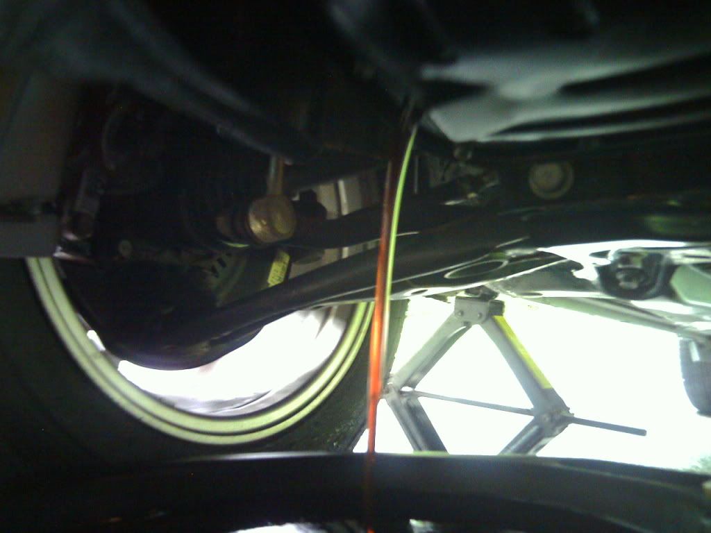 STEP THIRTY-FIVE: ---Remove OEM oil pan -The pan is held on by 8x 10mm bolts and 2x 10mm nuts. When you get them all off, you’ll notice the pan is still attached to the block pretty firmly. There’s a layer of sealant/adhesive that is holding it in place. I grabbed a flat head and rubber mallet and worked it into the cracks. Eventually I had enough leverage to pry it off. Dump out any remaining oil in the pan. 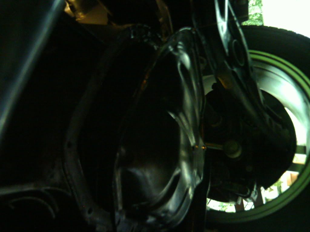 STEP THIRTY-SIX: ---Clean any and all oil where the pan bolts up -Pretty self-explanatory. Grab a rag or some paper towels and clean around the bolt holes on the engine block. You need this surface to be as clean as possible for the sealant we’re going to be using. STEP THIRTY-SEVEN: ---Remove OEM "studs" from engine block -Oh dear god, this was awful. If you have a M4 female torx socket on hand, then you just saved yourself a lot of aggravation. Otherwise, you're in for some fun. Believe it or not, the studs that the OEM oil pan nuts go on can be removed from the engine block, and need to be. I tried a lot of things, but I finally got them out with a big meaty vice grip. STEP THIRTY-EIGHT: ---Assemble the Zage oil pan -*UPDATE: TAP THE BLOCK. DON'T USE ZAGE'S PAN. -For starters, attach the silver return flange to the bolt hole on the side (the flat one). Don’t forget to put the black paper-like gasket first. Also bolt in the drain plug. Like the OEM pan, it’s 14mm as well. Next, refer to the third picture. The return elbow CANNOT go any lower than this angle, or else gravity will not be able to return the oil successfully. Get it angled in this manner now, so you know what your lowest angle is when you attempt to connect the return line later. 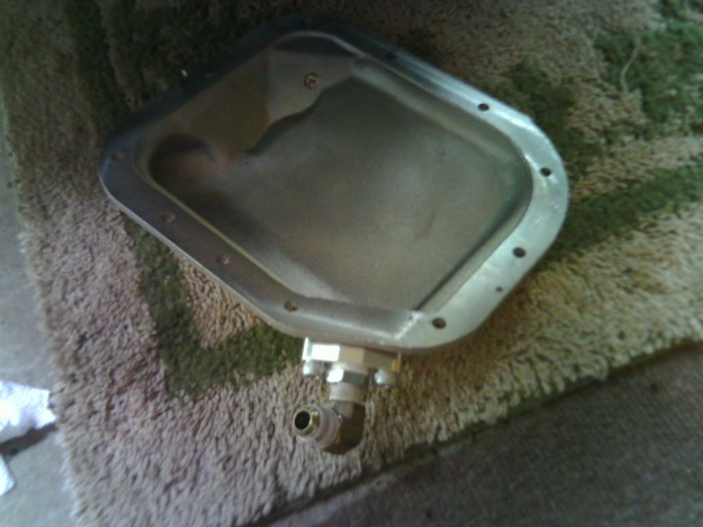 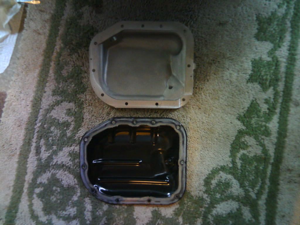 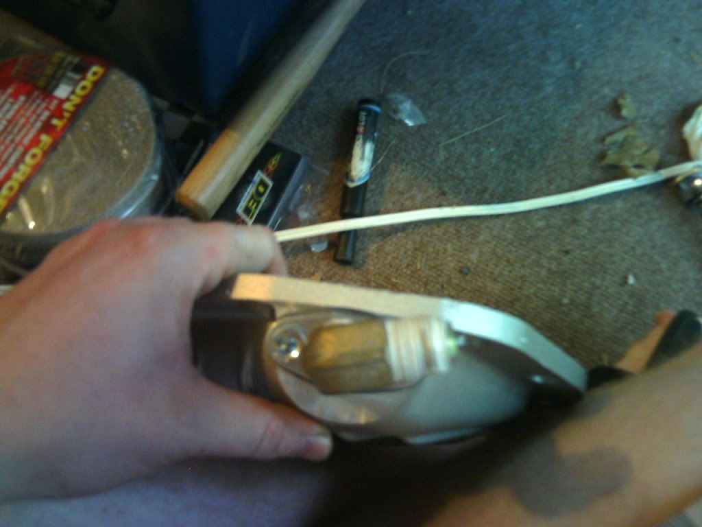 UPDATE: After months of debating whether or not to use this pan, I've decided it's best not to use it. Unfortunately, the return line is simply a bad design and was causing excessive turbo blow by. I'd recommend tapping the block right from the get go. This will make future oil changes easier as well (otherwise, you have to remove the return fitting at the pan to remove the oil filter). I didn't take any pictures, but you're going to need a drill, 90 degree attachment, and 3/4 drill bit. Here's the fittings you're going to need (you also need to assemble your own hose - mine was about 6"). Thanks goes to Brian. Quote:
Quote:
STEP THIRTY-NINE: ---Apply silicone sealant to Zage oil pan -*UPDATE: TAP THE BLOCK. DON'T USE ZAGE'S PAN. -Grab your sealant and put a healthy blob around the entire edge of the Zage pan. Don’t worry about spreading it, this will be done when you press it against the engine block. Hint: you’d rather use too much than not enough. Now apply a good size blob on each bolt and nut. STEP FORTY: ---Attach Zage oil pan to engine block -*UPDATE: TAP THE BLOCK. DON'T USE ZAGE'S PAN. -With the surface clean and the sealant applied, push the pan into place. Thread two bolts on the opposite sides of the pan with your fingers so it’s held in place. Now get all bolts on, and get them all semi-tight. You don’t want them to be too tight, because you want the sealant to cure before tightening the pan. Walk away/ continue the install at this point, but come back to the pan in about four hours and tighten all bolts. Also, feel free to reattach the oil filter at this point. STEP FORTY-ONE: ---Cut engine block to accommodate for oil return line -*UPDATE: TAP THE BLOCK. DON'T USE ZAGE'S PAN. Therefore this step is unnecessary. -Using a hacksaw and a drill, cut away the area of the engine block as seen in the pictures. I hacksawed two slots, then drilled away the bottom until a rectangular shaped piece fell out. I’m not entirely sure if this is needed, but by doing this you keep the oil return line sloping downward at all times, allowing gravity to do work. 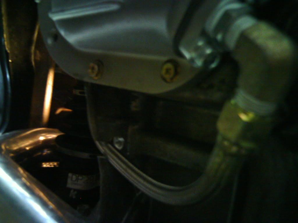 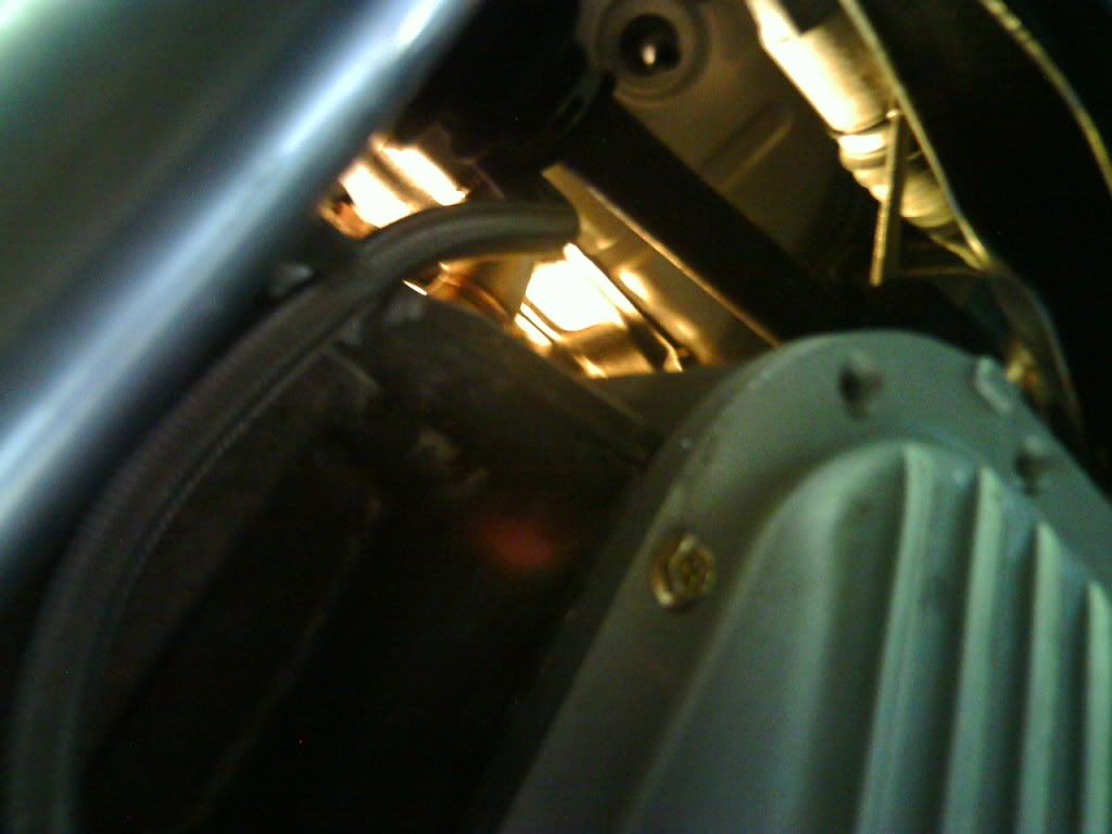 * While you’re down there, you really should fashion up a bracket to keep the oil feed and return lines away from the axle, otherwise they’ll get sheared. I used one of the threaded stems that held part of the black frame that we removed in the beginning, and attached a bracket similar to the ones I used for the intercooler. I just reused the nut to hold the bracket, then sent two zip ties through two separate holes wrapped them around the feed and return lines. After tightening the zip ties, those lines won’t be moving at all. 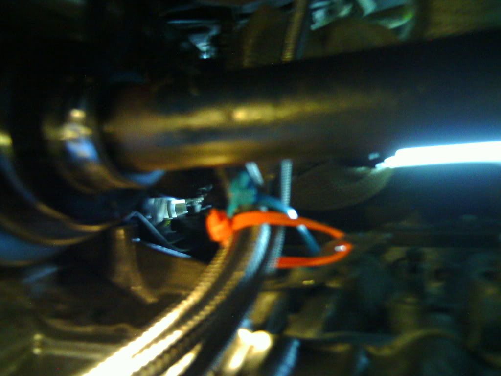 STEP FORTY-TWO: ---Attach oil return line to pan --*UPDATE: TAP THE BLOCK. DON'T USE ZAGE'S PAN. -Your oil return line should already be attached to the turbo, so it’s just a matter of manipulating it a bit. Make sure it runs through that slot we just cut, and play with it a bit until its lined up with the elbow. Remember, don’t move the elbow downward anymore than it already is (upward is ok). Thread it onto the elbow, and use a 15/16” wrench to tighten the line. STEP FORTY-THREE: ---Attach oil feed line -Your oil feed line should also already be attached to the turbo. If your oil filter isn’t back on yet, do it now. Run the oil feed line with the oil return line (under the block) and next to the filter. You’ll be needing a ½” wrench to get one of the bolts off the sandwich adapter. You really should prepare the oil feed tee first. It’s as simple as leaving the top spot open, putting the included bolt (in the oil return bag) in one side, and the 1/8” NPT male to 1/8” NPT male adapter into the other side (same bag). Once you have an open spot on the sandwich adapter, screw in the oil feed tee we just prepared, tight, using some pliers. Make sure the open spot faces downward. Thread the adapter with the flared end (flared end into oil feed line) first. Then thread the other side into the open end on the tee. I can’t remember what size wrench is used to tighten the feed line. 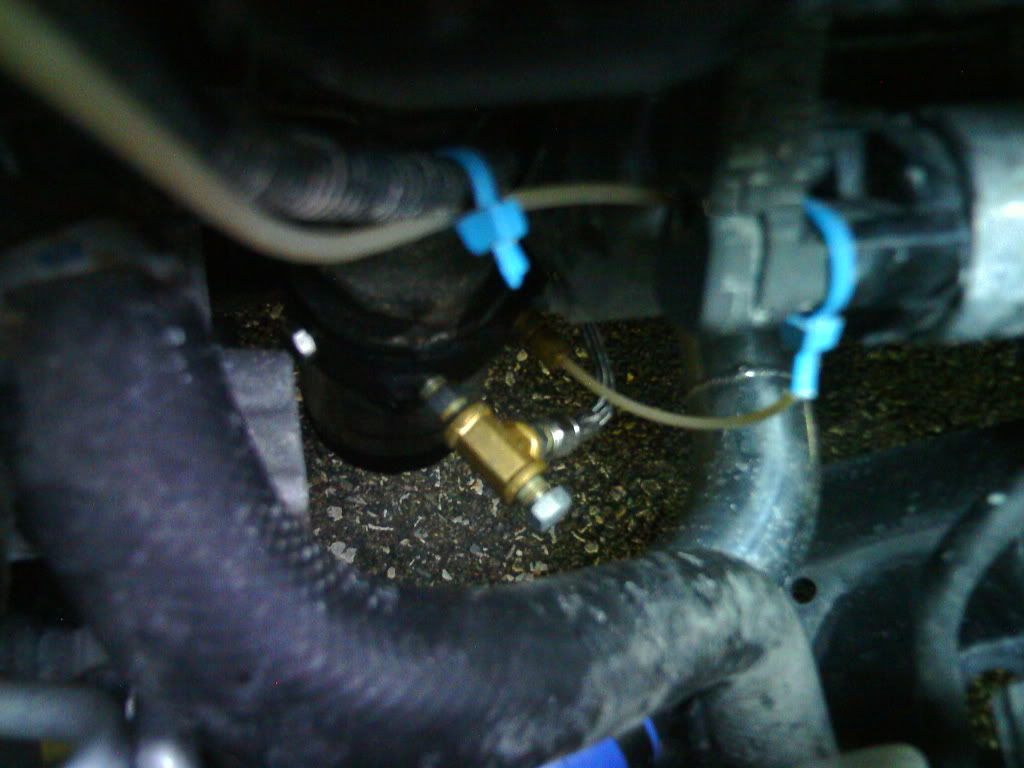 @Oil lines are now complete. We’ll shift our focus onto the coolant lines. I’m going to assume that at STEP NINETEEN you attached the downwards facing adapter and attached some rubber hose to it. I’d like to add we’ll be tapping the throttle body coolant lines. I found them the most accessible. STEP FORTY-FOUR: ---Lower car STEP FORTY-FIVE: ---Attach upwards facing coolant adapter (if water cooling) -Grab at least three feet of hose and push it onto the barb. Next, attach the adapter to the turbo (in the only available slot). I can’t remember entirely, but you may have to put the adapter in first, then add the rubber hose (the firewall may be in the way). 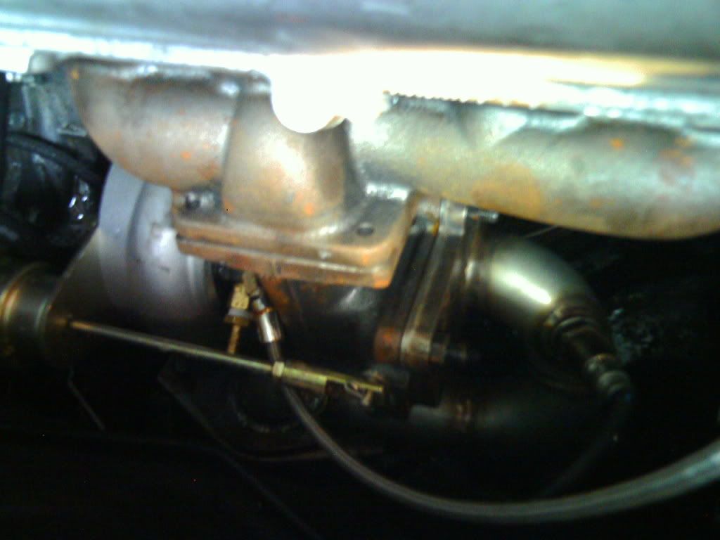 STEP FORTY-SIX: ---Place nylon tees in throttle body coolant lines -Cut each coolant line at an easy to reach place using an exacto knife or tool of choice, then place a 5/16” nylon tee in each. UPDATE: By using nylon tees, you're plumbing the coolant in parallel. I believe I had some leaks as a result of this because at certain points in the lines there would probably be weird pressure differentials. So, I redid this by plumbing everything in series instead. Basically, it's now set up like this: TB IN --> TB OUT --> TURBO IN --> TURBO OUT --> ENGINE IN. "Turbo in" is the line on the top, while "turbo out" is the line that comes out the bottom of the turbo. As for the TB, check this picture out (Thanks H3llion).  STEP FORTY-SEVEN: ---Run the turbo coolant lines and attach to nylon tees (if water cooling) -You need to run the turbo coolant lines on the right side of the engine, under the fuel rail, evap hose, wiring harnesses, etc. etc. Attach each one to one of the nylon tees. It doesn’t matter how you connect the hoses, as one will be coolant in and one will be coolant out. On top of that, it doesn’t matter which way coolant flows through the turbocharger, just as long as it flows. 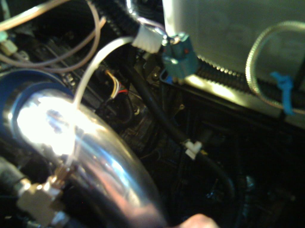 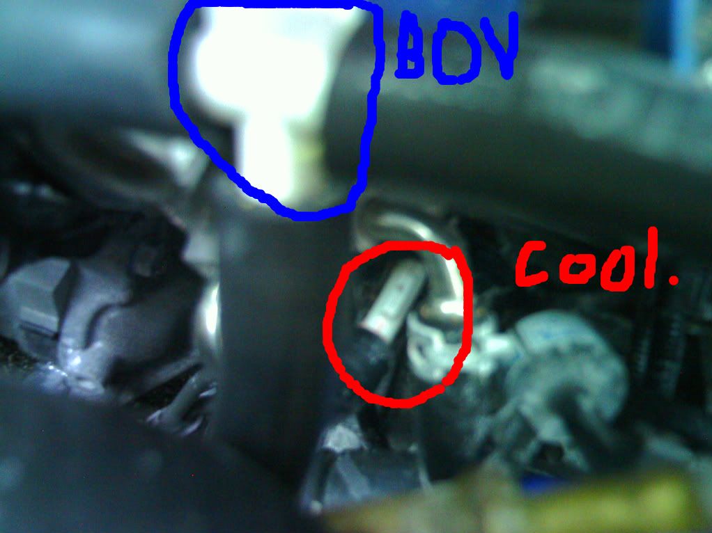 @Coolant lines are now complete. Time to work on the blow-off valve. STEP FORTY-EIGHT: ---Cut and place nylon tee in vacuum hose -Cut the vacuum hose and place a 5/16” nylon tee in line. Have the tee facing downward. Don’t get confused by my picture, I have a brass tee I use for my boost gauge in line as well. 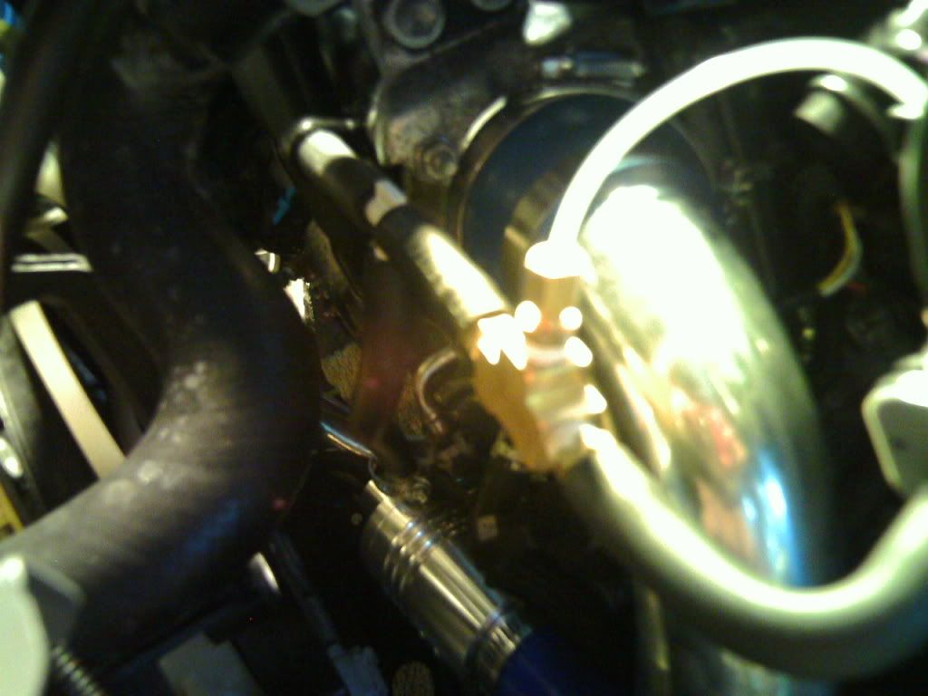 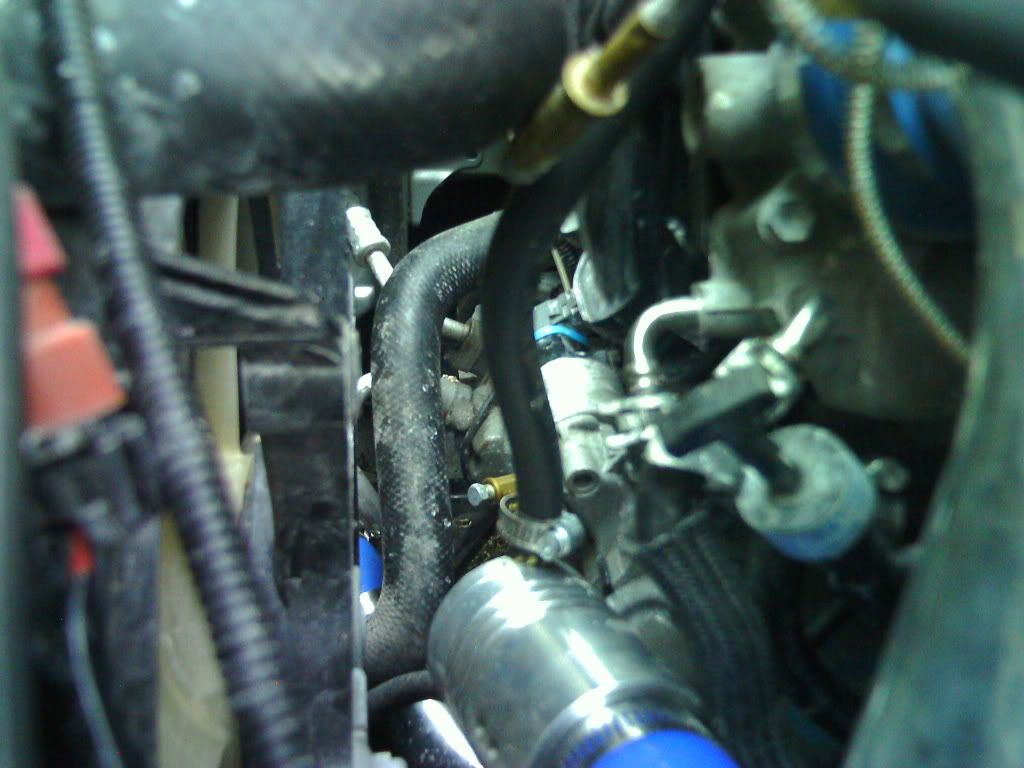 *UPDATE: The other crappy part of this kit is the BOV. It sucks (no pun intended lol). Buy yourself a decent one. I bought a SSQV III and a 30(?) mm flange so that you can pop it right into where the ZAGE BOV would go. STEP FORTY-NINE: ---Attach rubber hose from blow-off valve to nylon tee. -Cut just enough hose to go from the blow-off valves up to the nylon tee. Push the hose onto the nylon tee, it will be a snug fit. However, the barb on the blow-off is for a 3/16” hose, and we’re using 5/16”, so put a mini t-clamp at the bottom of the hose. *I was worried I had a vacuum leak, so I ended up buying a nylon tee from Advance auto that has multiple barbs. It allows you to trim the barbs to get either a 1/8, 1/4, or 3/8 barb. I cut one side to 3/8 for the OEM vacuum hose (yes it's 5/16, but it fits on 3/8 perfectly), and cut the other two sides to 1/4. I ran a 3/16 hose to the BOV, and the other runs to my FIC MAP sensor. @Blow-off valve is done. Next is the air filter needs to be put together. STEP FIFTY: ---Put together air filter assembly -First things first, grab the MAF and attach it to the piece of pipe with the rubber gasket, using the two mounting screws included. Next, push the air filter onto the rubber gasket and tighten the t-clamp. Take one of the huge, elbow silicon couplers and push it all the way up to where the MAF mounts. Grab the only pipe remaining and push it into the other side of the coupler. You’ll notice there is a bung on the pipe (for the evap hose). Do not push the pipe so far into the coupler such that its touching this bung. Leave about an inch of clearance, otherwise when you put the assembly in the battery gets in the way. 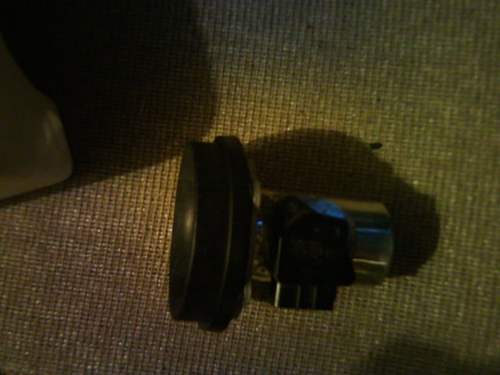 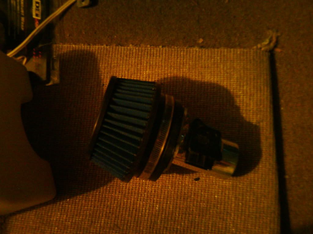 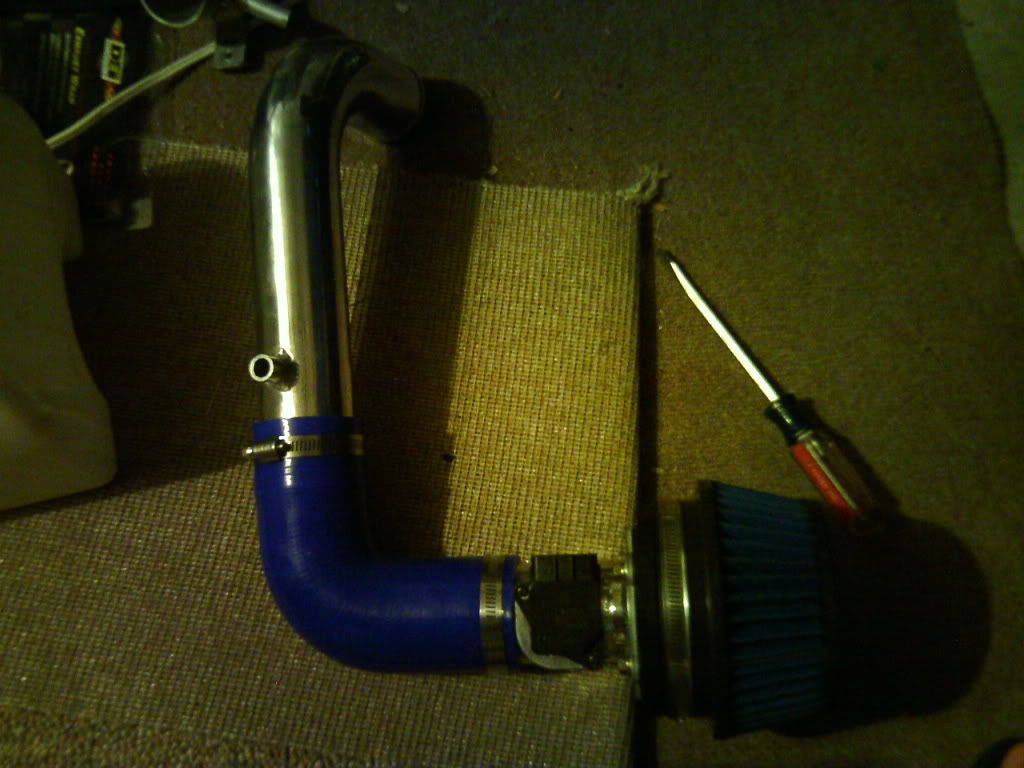 STEP FIFTY-ONE: ---Attach silicone coupler to compressor side of turbocharger -As you can immediately see from the picture, it’s incredibly difficult to get at the compressor outlet from the top of the engine. It’s also impossible to get at it from the bottom. I moved whatever hoses and wires out of the way that I could. Next, I put a t-clamp on the compressor inlet. Then I attached the silicon coupler and pulled the t-clamp onto the coupler. You’re gonna need to wiggle the coupler around a bit until you finally get it in place, then wiggle it some more to get it onto the compressor inlet. Spin the t-clamp until the bolt is in a convenient spot. No matter what, it will be in a very difficult to reach spot. I practically climbed into the engine bay to be able to reach it. STEP FIFTY-TWO: ---Attach air filter assembly to outlet coupler -Reaching the aforementioned coupler is a little easier to do when you’re just pushing a pipe into it. Don’t forget to t-clamp it as well. Also plug the MAF back in now. 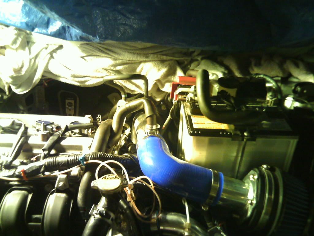 UPDATE: I ended up connecting one of the PCV lines to a mini breather filter (as opposed to rerouting it back into the intake piping) and routed the other PCV line through an oil catch can. I would at least recommend adding the mini breather filter. My set up is similar to the one below (Thanks PETERPOOP for the pic). 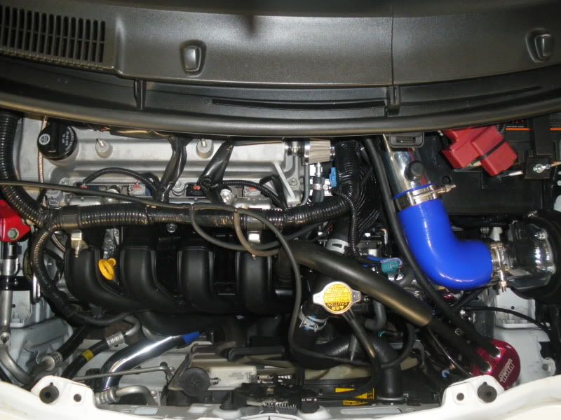 @At this point I’d like to say congratulations if you made it this far. The whole kit is now installed; however there are a number of things that remain to be done before you can fire up the engine. I’ll continue to cover what I did and the necessary steps. STEP FIFTY-THREE: ---Pull spark plugs -You just need to remove the wiring harnesses from the spark plugs. They’re right on top of the engine. Use pliers if you can’t get them off by hands. They only have one clip. STEP FIFTY FOUR: ---Pull EFI fuses -These two fuses are located in the engine bay fuse box. Consult my picture or the fuse box cover to know where they are. Use the fuse remover in the box to aid in removing them. 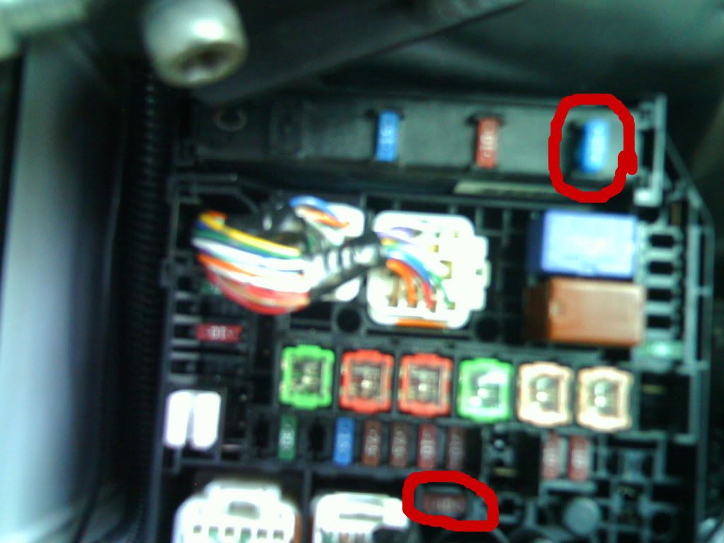 STEP FIFTY-FIVE: ---Prime the turbo -THIS IS INCREDIBLY IMPORTANT. This step could very well determine whether or not your turbocharger blows or not on the first start up. The last two steps were prep for this. What you now need to do is crank the engine long enough to get the oil pump working. If you have a mechanical gauge installed, this will be easier. Turn and hold the key to ignition. The car won’t start, but the starter will attempt to do so. Watch your gauge build pressure. When it reaches 20 psi, stop cranking. Count out 10 seconds, then repeat. Do this process five times. If you don’t have a gauge installed, count out about 15 seconds while cranking, then stop. I found this to be about how long it took to build 20 psi of oil pressure. *I had an interesting experience with priming the turbo again about a month after the install. I had just done an oil change, and just to be safe, was going to prime the turbo. The above procedure DID NOT work. The engine cranked, but I was unable to build oil pressure. If you experience the same issue, leave the EFI fuses in, but unplug the fuel injectors. UPDATE: You don't need to prime the turbo every time you do an oil change, only before the initial start up. STEP FIFTY-SIX: ---Replace EFI fuses and spark plugs -Do the above, and check all other connections. Make sure the O2 sensor is plugged in, and the vacuum hose is attached. STEP FIFTY-SEVEN: ---Start the car -This is it. Everything you’ve done up until this point now all converges here. Yes, it’s incredibly nerve-racking. Trust me though, you’ll want to hear your new turbocharger rawr for the first time. Hopefully everything was done right. You should know almost immediately. Good luck. STEP FIFTY-EIGHT: ---Diagnose leaks -This, arguably, took me the longest to deal with. I’m not sure what the right way to go about this is. Basically, you need to start the car and let it run, and watch for coolant and oil leaks around the oil pan, oil filter, throttle body coolant tees, and turbocharger. The best way to deal with a leak is to first see if you can tighten whatever connection may be leaking. If not, the next step is to replace the adapter / fitting / line that’s leaking. STEP FIFTY-NINE ---Exhaust wrap hot side -This should only be done when all leaks have been 100% dealt with. The only exceptions being the AC lines and O2 sensor wires. Otherwise, you’ll want to get a good amount of wrap around the turbine housing, the manifold, and the downpipe. It's not necessary to take the turbo assembly out to wrap it. *Getting the wrap wet makes it this an easier task. It can be wrapped tighter as well. 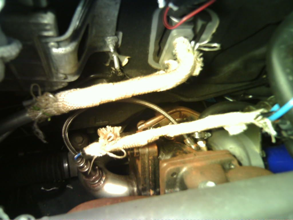 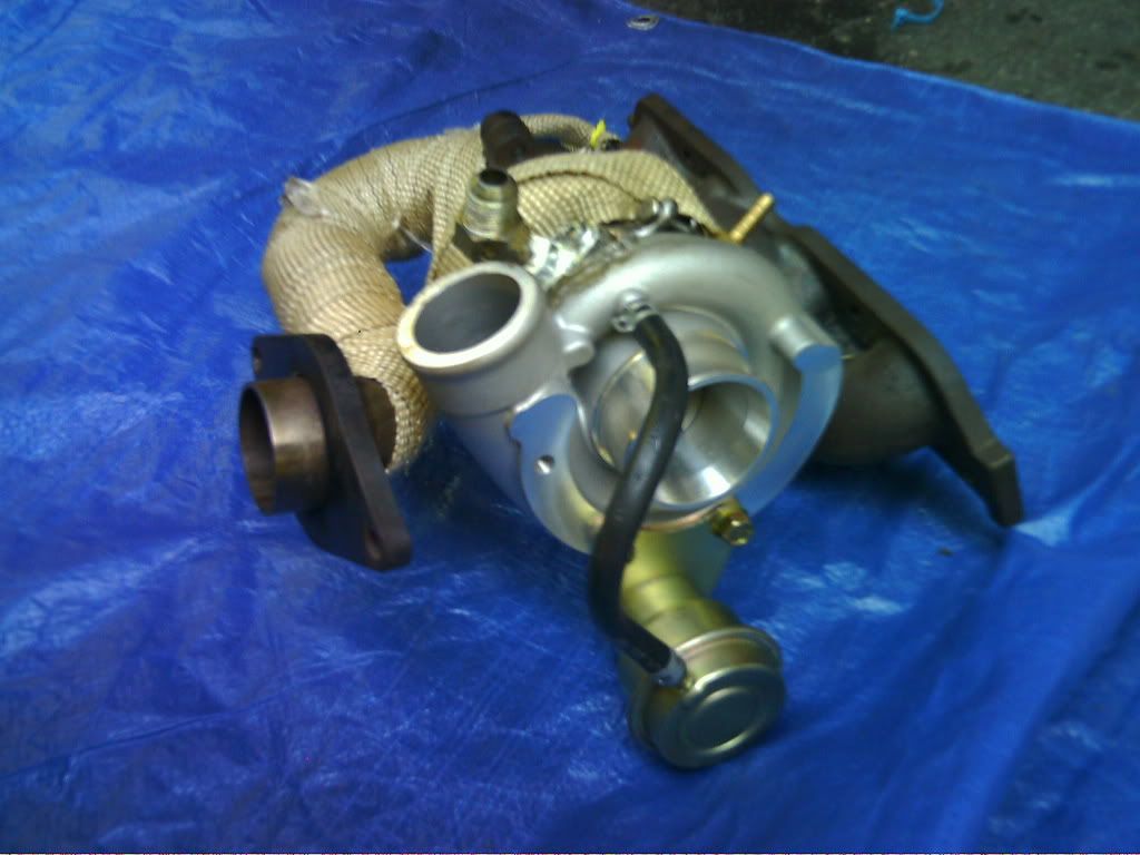 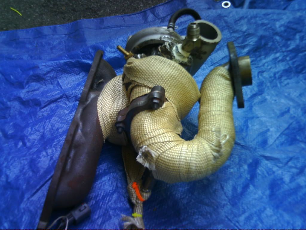 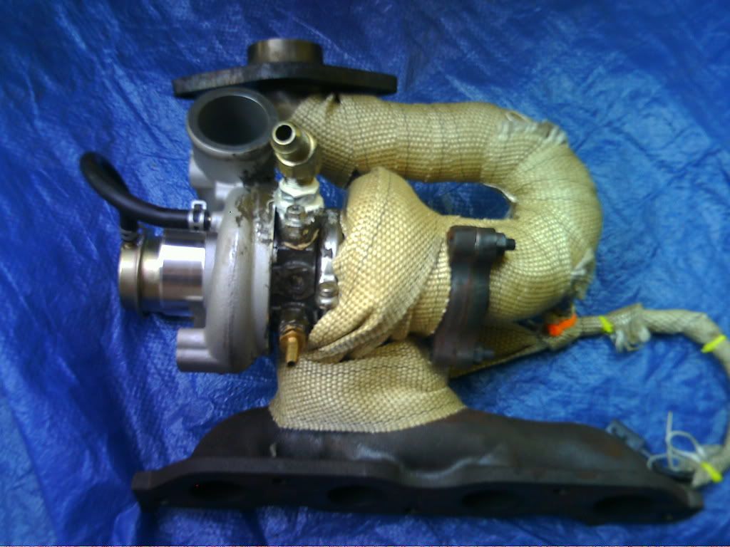 * O2 Sensor: I was having problems with wires burning when I was running the O2 sensor wires, exhaust wrapped, over the turbo and manifold. I ended up extending the wires and running them through some plastic flame retardant conduit. I ran that away from the downpipe, up towards the ECM, and across the top of the engine bay and connected the molex connectors near the power-steering fluid tank. I also exhaust wrapped the conduit. Overkill maybe, but I haven’t had any problems since. 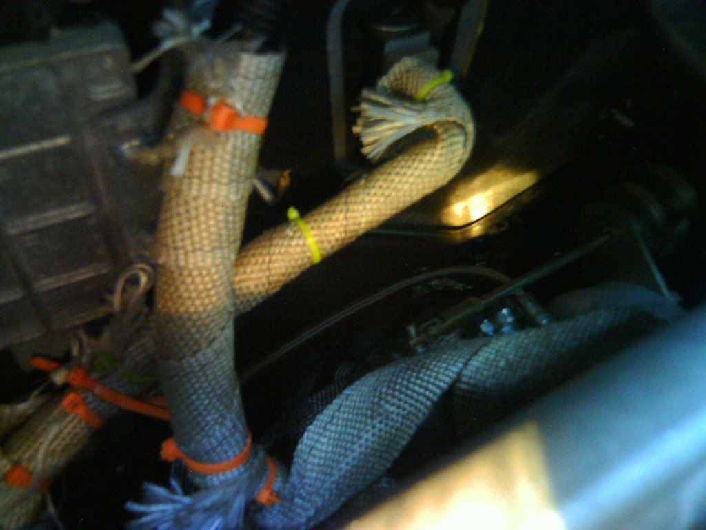 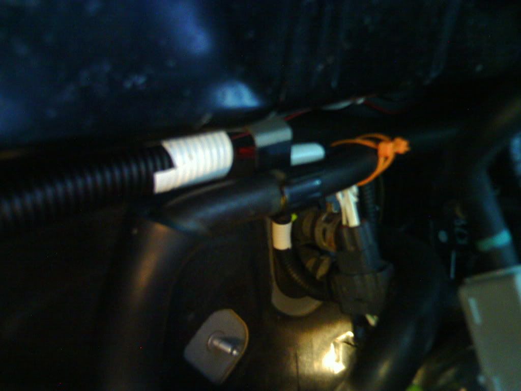 STEP SIXTY: ---Get Tuned -That’s about it. As soon as the car becomes drivable, your priority list becomes 1) fill up on premium and 2) get tuned. It’s probably safe to drive the car around a little bit and enter boost once you have premium gas, but the sooner you get tuned, the better. Plus, it’s most likely going to give you an additional increase in performance. UPDATE: I'm running plus (89 octane) with no issues. *UPDATE: I'd still recommend 93 though. STEP SIXTY ONE: ---Enjoy your newly boosted Yaris! -This is probably the easiest step of the guide. Trust me, the first time you enter boost in this car, your face is going to hurt from smiling so much. Hard work pays off! Last edited by Focus_Sh1ft; 11-21-2012 at 01:18 PM. |
||
|
|

|
|
|
#2 |
    Drives: 08 Yaris Turbo; 06 tC Turbo Join Date: Jan 2010
Location: New Jersey
Posts: 875
|
-----ADDITIONAL INFORMATION / RESOURCES-----
---EXPENSES--- (this is what I paid)
-Zage turbo kit - $1600 shipped -Custom Exhaust - $200 -Flowmaster Super 44 - $85 -Professional Tuning - N/A (Tuned myself) -AEM FIC - $320 -AEM UEGO - $195 -Boost, Water Temp, Oil Pressure gauges - $60 -Filter Sandwich adapter - $30 -A-gauge pod - $20 -Turbo Timer - $40 (optional) -1ZZ Injectors - $50 (optional) -Exhaust Wrap - $30 -6.5 ft of rubber fuel hose -$30 -Teflon Paste - $7 -Silicone Sealant - $5 -3x Nylon Tees - $5 -8x hose clamp - $5 -Brass fittings - approx. $2 ea. -AC Refrigerant - $20 -Code Reader - $60 (cheapest at Advance Auto) Estimated total - $2772 ---WORD COPY OF GUIDE--- I've taken this guide and thrown it into a word 2007 document (.docx) with the pictures embedded. It's a 30 MB file, so I had to upload it kinda weird. -Download these 9 .zip files -Remove JUST the .zip extension -Download WinRAR if you don't have it (or similar file extracting / compressing program) -If WinRAR installed, right click one of the files and click "extract here" -Open the word document *If your computer sucks, it may take awhile to open. Last edited by Focus_Sh1ft; 11-16-2010 at 08:17 PM. |
|
|

|
|
|
#3 |
    Drives: 08 Yaris Turbo; 06 tC Turbo Join Date: Jan 2010
Location: New Jersey
Posts: 875
|
Alright well here's my tune for anyone interested. I'm pretty satisfied with it at this point.
Specs: -AEM FIC Fuel map -Zage Turbo Kit -AFR Sensor unplugged -1ZZ Injectors (240-260cc; stock: 200cc) -MBC set to about 8 psi (probably irrelevant) -Automatic (should work just as well for manual) I've set this tune up to get both the best of performance and fuel economy. At any point outside of boost, I've aimed for 14.7 (stoich) for emissions and fuel economy purposes. Here's how I have boost arranged... 1 psi - low 14s, high 13s 2 psi - Around 13.5 3 psi - low 13s, high 12s 4 psi - 12-12.5 5 psi+ - Around 11.5 I thought this was pretty reasonable considering after a couple of months driving around without a tune, stoich seemed to be fine up to 5 psi. Obviously the greater the air is compressed, the more heat is produced, so additional fuel (for cooling) should be added. I've definitely noticed a performance increase by running richer AFRs as well. Hopefully this tune will be largely plug and play, but if not, I'd like to point out how I went about this. ANYONE can do this (with a wideband, of course). -Hook laptop up to FIC to log the run (I never used the internal logger). -Log the run. I honestly just did this during normal driving. You're going to want some spots where you're boosting, and simply cruising. -Open the log up in excel and hide all data except RPMs, fuel trim, wideband, and engine load. -Look for areas in the log where the breakpoints on the fuel map approximately match up. Then look at the fuel trim on excel and the map. Subtract points from the map at that location to lean the mixture, add points to richen the mixture. I never added/subtracted too much at once - you only want small changes until you reach your desired AFR. ***This is a weird glitch in the coding of the FIC I discovered (pimp my yaris also had this problem). Everywhere you see a .8, leave it alone. It's simply there to prevent the following. Apparently, when the FIC is fueling and it gets dropped to 0 (i.e. accelerating then letting off the throttle) it freaks the hell out. I noticed it was just dumping fuel at AFRs richer than 10. My engine was stuttering badly until I replaced all the zeroes with .8. At this point, the only way I can make a Zage turbo kit install easier is by showing up and doing it myself lol. DISCLAIMER: I'm not responsible for any problems that may arise from using my tune. It's tried and tested, but not stupid-proof. Last edited by Focus_Sh1ft; 11-16-2010 at 09:34 PM. |
|
|

|
|
|
#4 |
       ULTIMATE ULTIMATEDrives: 07 Yaris Turbo Join Date: May 2007
Location: Canoga Park, CA
Posts: 14,859
|
nicely done.
what does reserved mean? oh, and throw all that into a Word doc and save as a PDF
__________________
Micro Image forums, online store and shop are now closed. It was a great eight year run, but it was time to focus on other things. I'm still selling parts on eBay under micro*image seller ID and customers can still make requests for anything specific. |
|
|

|
|
|
#5 | |
|
Mr. 155 and climbing
Drives: Seriously Modded 07 Sedan Join Date: Jun 2006
Location: In The Hotbox
Posts: 4,742
|
Quote:
I read thru your preface and it looks like you did a good job.  Some might be interested in a ballpark figure of your expenditures; both money and time.
__________________
Team Tiamat Racing on Facebook Youtube Channel: Team Tiamat Racing Class record holder in Land Speed @ 154.5mph for 1.5 mile and 145.5mph in the mile in the F (2.016 to 3.014 L), G (1.524 to 2.015 L), and H (1.016 to 1.523 L) classes. |
|
|
|

|
|
|
#6 |
    Drives: 08 Yaris Turbo; 06 tC Turbo Join Date: Jan 2010
Location: New Jersey
Posts: 875
|
Haha give me time guys, I'm still inserting pictures.
I was just attempting to throw my .docx version in as an attachment, but I currently have to get over the size limitation hurdle. The guide is 30 mb (the pictures are embedded), and I even tried compressing it, splitting it, then renaming the extension to .zip so I COULD upload to the site. No dice. I'll think of something. |
|
|

|
|
|
#7 |
   Drives: 09 YarHB Join Date: Feb 2009
Location: Canada
Posts: 175
|
Focus...
Have you tuned it yet? Numbers?? mmmmmmmmm Numbers.. :P |
|
|

|
|
|
#8 |
  Drives: '09 Blazing Blue 3D LB Join Date: Apr 2009
Location: Tucson, AZ
Posts: 64
|
Awesome man! Your original thread is what got me finally doing the install. I'm hoping to follow in your footsteps and be completely installed and tuned by the end of October.
|
|
|

|
|
|
#9 | |
    Drives: 08 Yaris Turbo; 06 tC Turbo Join Date: Jan 2010
Location: New Jersey
Posts: 875
|
Quote:

|
|
|
|

|
|
|
#10 | |
       ULTIMATE ULTIMATEDrives: 07 Yaris Turbo Join Date: May 2007
Location: Canoga Park, CA
Posts: 14,859
|
Quote:
__________________
Micro Image forums, online store and shop are now closed. It was a great eight year run, but it was time to focus on other things. I'm still selling parts on eBay under micro*image seller ID and customers can still make requests for anything specific. |
|
|
|

|
|
|
#11 |
|
C'est la vie
Drives: 2009 2 door hatchback Join Date: Aug 2009
Location: chicago
Posts: 482
|
Nice thread. Very detailed. Just wanted to mention if U get the header wrap wet if is much easier to install and U can wrap it tighter. Pics look so familar. I cant believe my turbo set up looks so much like the zage kit, considering I never saw it before. It looks like their manafold is a little shorter and may be a little roomier under the hood. But who knows about flow.
Next question, Who's going for pistons and rods first? I think I will need a beefier clutch first though. |
|
|

|
|
|
#12 |
       ULTIMATE ULTIMATEDrives: 07 Yaris Turbo Join Date: May 2007
Location: Canoga Park, CA
Posts: 14,859
|
Clutchmasters is the best I've tried, definitely way better than Exedy.
__________________
Micro Image forums, online store and shop are now closed. It was a great eight year run, but it was time to focus on other things. I'm still selling parts on eBay under micro*image seller ID and customers can still make requests for anything specific. |
|
|

|
|
|
#13 |
   Drives: yaris1.33 Join Date: Jul 2010
Location: slovakia
Posts: 425
|
very nice
what is the HP increase after install ? |
|
|

|
|
|
#14 | |
    Drives: 08 Yaris Turbo; 06 tC Turbo Join Date: Jan 2010
Location: New Jersey
Posts: 875
|
Quote:
As for rods and pistons... I doubt I'll ever be doing that, but don't quote me. I've been playing around with ideas and so far have only really come up with meth injection, and possibly a lightweight flywheel. I am, however, very interested in the Gude head, but H3llion seems to have fallen off the face of the planet. I'll get the numbers when I get tuned. Should be next week hopefully. And Garm, to answer your two questions - I'm using a narrowband because 1) I'm not tuning myself and 2) I see no reason to spend $200 on one. As long as I know whether I'm running lean, rich, or stoich, I'm happy. I tried making the guide a PDF but it didn't save much space. Lots of pictures = lotsa MBs. A fair trade off. 
|
|
|
|

|
|
|
#15 |
   Drives: 09 YarHB Join Date: Feb 2009
Location: Canada
Posts: 175
|
Focus,
I downloaded the files.. Weird, The doc's are all corrupt. Will try again, then I might be able to do a combine and compress with bullzip. FYI ;) |
|
|

|
|
|
#16 |
   Drives: 09 YarHB Join Date: Feb 2009
Location: Canada
Posts: 175
|
Split into two
lets try these on for size.. :P
The pics are pretty high res. Sorry, best I could do at work! |
|
|

|
|
|
#17 |
|
School'er of hard knocks
Drives: Silver Yaris 4dr. HB Join Date: Oct 2008
Location: Sudbury, On
Posts: 556
|
Are you sure you can tune that with just the FIC?
I was sure an E-manage was a necessity when boosted... For reliability without a check-engine light... |
|
|

|
|
|
#18 | |
       ULTIMATE ULTIMATEDrives: 07 Yaris Turbo Join Date: May 2007
Location: Canoga Park, CA
Posts: 14,859
|
Quote:
__________________
Micro Image forums, online store and shop are now closed. It was a great eight year run, but it was time to focus on other things. I'm still selling parts on eBay under micro*image seller ID and customers can still make requests for anything specific. |
|
|
|

|
 |
|
|
 Similar Threads
|
||||
| Thread | Thread Starter | Forum | Replies | Last Post |
| NEWS: TOYOTA REVEALS ALL-NEW YARIS SEDAN AT 2006 LOS ANGELES AUTO SHOW | VitzBoy | General Yaris / Vitz Discussion | 7 | 09-20-2023 07:50 AM |
| Turbo kits!! | djgab101 | Forced Induction Forum | 26 | 03-09-2015 03:24 PM |
| 2007 Yaris Pricing Info ! | YarisBueller | New YARIS Purchase Forum | 104 | 06-24-2009 04:54 PM |
| Turbo kit Brainstorming | Gideon | Forced Induction Forum | 16 | 04-19-2009 12:54 AM |